
Water Heater Venting Assembly

a technology for venting assemblies and water heaters, applied in fluid heaters, combustion processes, combustion treatment, etc., can solve the problems of increasing the installation time and cost of associated equipmen

Active Publication Date: 2017-12-14
IPEX TECH
View PDF8 Cites 6 Cited by
  • Summary
  • Abstract
  • Description
  • Claims
  • Application Information

AI Technical Summary

Benefits of technology

The present invention provides a water heater venting assembly that can overcome shortcomings of existing duct works or venting assemblies. It can adjust to different water heaters with varying duct dimensions and locations. It can direct combustion air and flue gas between the water heater and outdoor atmosphere, reducing installation time and costs. It can also permit monitoring of flue gas without necessarily requiring disassembly.

Problems solved by technology

In particular, with duct works provided a pair of conduits for connecting to the respective outlet / inlet ducts, a single coaxial double wall pipes for traversing a wall of a residential building and a gas joint for fluidically coupling the conduits and the coaxial pipe, modifications may be required to be introduced various physical changes to the conduits, joint and / or coaxial pipe, thereby increasing associated installation time and costs.

Method used


Image

  • Water Heater Venting Assembly
  • Water Heater Venting Assembly
  • Water Heater Venting Assembly

Examples


Embodiment Construction

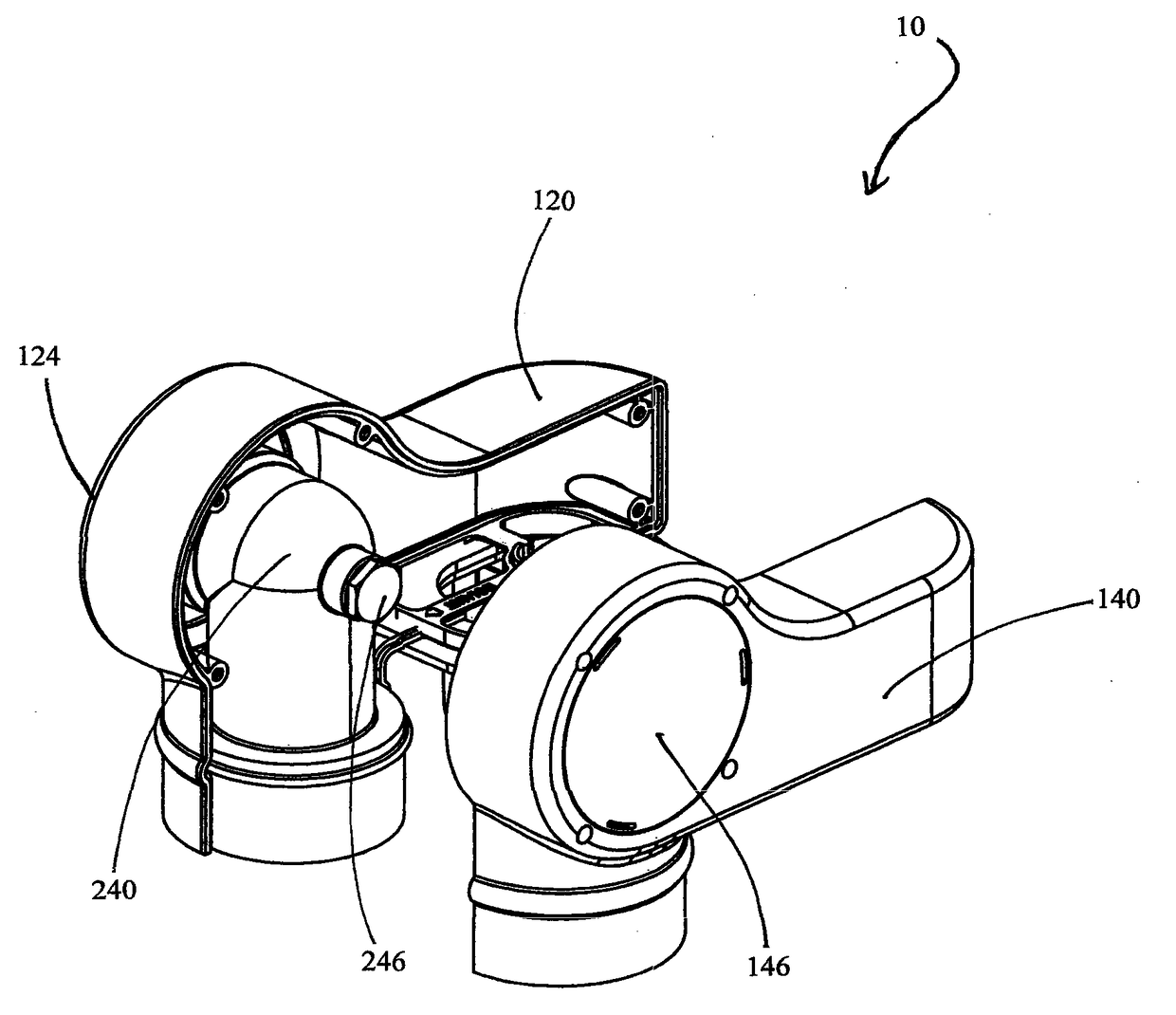
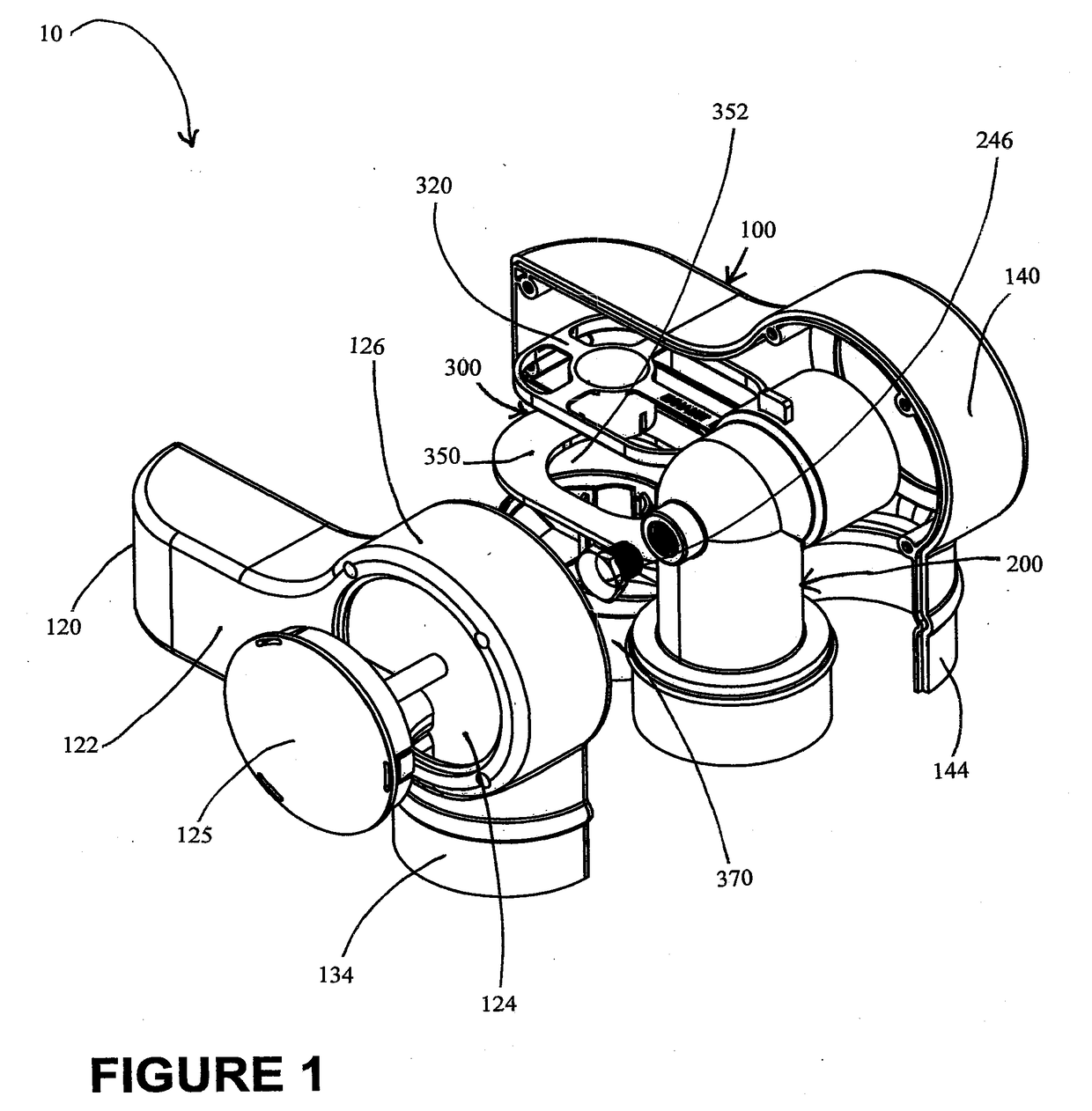
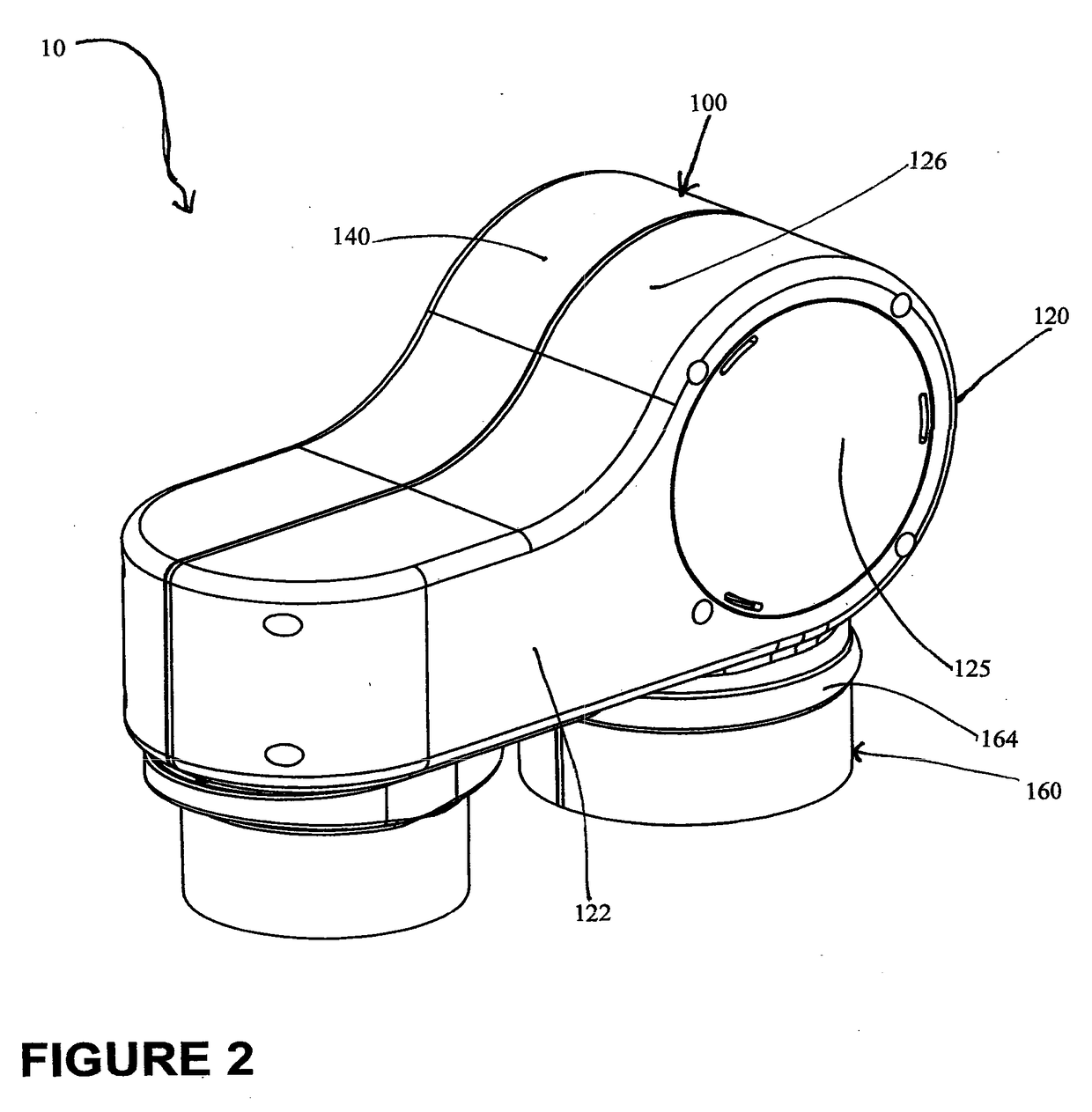
[0043]Reference is made to FIG. 1 which shows an exploded perspective view of a water heater venting assembly 10 for communicating a flue gas and a combustion air between a residential water heater and an outdoor atmosphere, in accordance with a preferred embodiment of the present invention. In the construction shown, and as will be further described below, the water heater venting assembly 10 includes a generally hollow assembly housing 100, a flue gas exhaust conduit 200 and a movable inlet duct coupling assembly 300, where both the conduit 200 and the inlet duct coupling assembly 300 are shaped for placement in or attachment to or near the assembly housing 100. For more complete illustration, the venting assembly 10 is shown in an exploded view with the assembly housing 100 in a disassembled arrangement to reveal the included conduit 200 and the coupling assembly 300, and without the water heater.

[0044]The assembly housing 100 includes opposed lateral housing shell casings 120, 1...


PUM


Abstract

In a preferred embodiment, there is provided a water heater venting assembly for directing a combustion air and a flue gas between an outdoor atmosphere and a water heater, and which includes a generally hollow housing defining a combustion air aperture, a flue gas exhaust conduit disposed in the housing, and an adjustable inlet duct coupling assembly having a retention member for placement in the housing proximal to the aperture, a gasket for placement around an outer periphery of the aperture and a combustion air supply member. The retention member is for retaining the supply member in fluid sealing engagement with the gasket to effect fluid communication between the aperture and the supply member, and is sized to permit slidable movement of the supply member relative to the gasket.

Description

SCOPE OF THE INVENTION[0001]The present invention relates to a water heater venting assembly for directing a flue gas and a combustion air between a water heater and an outdoor atmosphere, and which preferably includes a housing and an adjustable duct coupling assembly to permit fluidic coupling between a coaxial gas pipe, and water heater inlet and outlet ducts of varying distances between the ducts.BACKGROUND OF THE INVENTION[0002]In various parts of the world, a typical residential building receives potable water through a single water supply line connected to a water main forming part of a local distribution system. To generate hot water from the potable water for various domestic uses including showers and baths, a water heater may be utilized to heat the potable water above its initial temperature as received form the water main.[0003]Commercially available water heaters generally rely on thermal energy obtained from combustion of fossil fuels such as natural gas to heat water...

Claims


Application Information

Patent Timeline
Patent Type & Authority Applications(United States)
IPC IPC(8): F23J13/04F24H1/20F23J11/00
CPCF23J13/04F23J11/00F24H1/205F23J2211/10F23J2213/202F23J2213/203
Inventor LEUNG, MARTIN KWAN YUSTIEHL, IVAN LEE
Owner IPEX TECH
Learn More