Current sensor and a method of manufacturing a current sensor

a current sensor and current sensor technology, applied in the direction of rate of change measurement, measurement device, instrument, etc., can solve the problems of poor performance of pcb rogowski type coils, and achieve the effects of reducing external interference resistance, increasing demand, and reducing costs

Active Publication Date: 2017-12-14
ANALOG DEVICES INT UNLTD
View PDF7 Cites 27 Cited by
  • Summary
  • Abstract
  • Description
  • Claims
  • Application Information

AI Technical Summary

Benefits of technology

[0005]With the rapid rise in more sophisticated energy meters that report energy usage to a central network (so called smart meters), there is an increased demand for accurate and interference resistant current sensors. Furthermore, there is a drive towards producing such sensors using printed circuit board (PCB) technology and to utilize mass production surface mount technology (SMT) in order to drive down costs. Several examples of PCB Rogowski type coils are available. However, these PCB Rogowski type coils tend to suffer from poor performance, as the designers introduced compromises in the design of the Rogowski coil in order to accommodate transferring the coil onto a PCB arrangement. For example, resistance to external interference is reduced, largely because of an absence of any sort of compensation conductor, or the use of sub-optimal compensation conductor arrangements. For example, the compensation conductor may be provided as a loop outside of the measurement coil or in a plane offset from the central plane of the measurement coil.

Problems solved by technology

However, these PCB Rogowski type coils tend to suffer from poor performance, as the designers introduced compromises in the design of the Rogowski coil in order to accommodate transferring the coil onto a PCB arrangement.

Method used


Image

  • Current sensor and a method of manufacturing a current sensor
  • Current sensor and a method of manufacturing a current sensor
  • Current sensor and a method of manufacturing a current sensor

Examples


Embodiment Construction

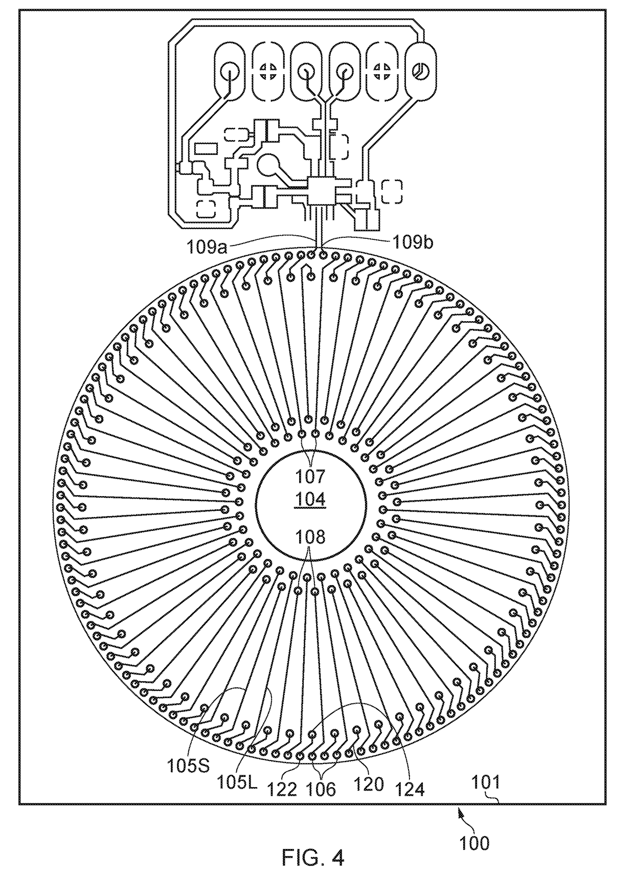
[0078]In an embodiment of the disclosure, a current sensor is provided using a single double sided circuit board (a board having tracks on only its opposing sides). The use of a single printed circuit board with only two conducive layers reduces cost and simplifies manufacture as the sensor can be on the same board that carries the processing electronics required to process the output of the sensor. Advantageously a toroidal current measurement coil is provided on the board. A compensation conductor is provided on the same board. The board includes an opening through which a current carrying conductor may pass. The compensation conductor is provided in association with the current measurement coil such that the average distance of the compensation conductor from the aperture is similar to the average distance of the coil advancement path formed between adjacent “turns” of the measurement coil. The compensation conductor may be formed in a number of different patterns, but typically ...


PUM


Abstract

The present disclosure provides an improved Rogowski-type current sensor. The current measurement coil, and the compensation coil are provided on the same board. The measurement coil and the compensation coil are arranged such that they at least partially overlap by virtue of each repeatedly changing side of the board. This arrangement makes the current sensor far better at rejecting interference than certain other PCB Rogowski type coil arrangements.

Description

RELATED APPLICATIONS[0001]This application claims the benefit of priority of U.S. patent application Ser. No. 15 / 179,249 (Attorney Docket No. 3867.298US1), which was filed on 10 Jun. 2016, the content of which is hereby incorporated by reference herein in its entirety.TECHNICAL FIELD[0002]The present disclosure relates to current sensors and methods of manufacturing current sensors.BACKGROUND[0003]A current sensor is an electrical device which detects and measures the electrical current passing through a conductor. Current sensors are required in many applications such as energy meters, electrical generators and circuit protection systems. There are two main types of current sensors. The first type introduces a “shunt” resistance into the circuit. This involves placing a resistor in series with the conductor, and measuring the voltage across the resistor. Shunts work well for currents under a few hundred amps. For higher currents, heating occurs in the shunt which makes accurate mea...

Claims


Application Information

Patent Timeline
Patent Type & Authority Applications(United States)
IPC IPC(8): G01R15/18G01R19/12G01R3/00
CPCG01R15/181G01R19/12G01R3/00
Inventor HURWITZ, JONATHAN EPHRAIM DAVID
Owner ANALOG DEVICES INT UNLTD
Why Eureka
Try Eureka