
Rendering based generation of occlusion culling models

Active Publication Date: 2017-12-14
MICROSOFT TECH LICENSING LLC
View PDF5 Cites 12 Cited by
  • Summary
  • Abstract
  • Description
  • Claims
  • Application Information

AI Technical Summary

Benefits of technology

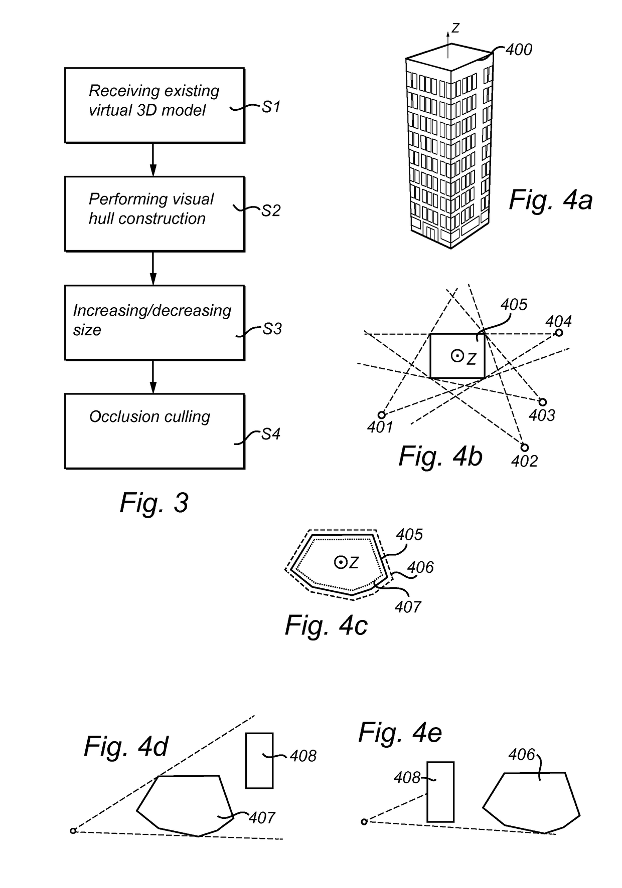
The present invention is a method and system for creating simplified representations of an existing virtual 3D model for use in occlusion culling. This is accomplished by using a visual hull construction based on the existing model and increasing or decreasing its size to create models of the object's occludees (the parts that are not visible) or imposters (the parts that are not important). These models are created automatically and efficiently, saving time and money during production for a virtual environment.

Problems solved by technology

A common trend for computer graphics is the increasing amount of complexity and therefore size of the computer graphic models.
The initial 3D models are computationally very expensive and thus require specialized graphics systems to handle, furthermore they are generally never able to be handled interactively.
The development of computer hardware is not likely to provide interactive handling of those 3D models since the size of the computer graphics and the size of the secondary computer memory is increasing at faster rates than the development of thereto related hardware.
These meshes are typically not optimized for display or simulation performance.
Drawing such a large number of polygons may be a task that is beyond the capacity of many of today's computer hardware systems.
However, the simplified versions are generally created manually by a graphical artist and their creation is labor intensive and the quality of the simplified version will depend on the skill of the artist.
Hence, the manual creation of the simplified representations is a tedious process and slows down as well as increases the cost when e.g. producing a computer game or similar.
In addition, the quality of the resulting simplified polygon representation is limited by the skill of the graphics artist.

Method used


Image

  • Rendering based generation of occlusion culling models
  • Rendering based generation of occlusion culling models
  • Rendering based generation of occlusion culling models

Examples


Embodiment Construction

[0035]The present invention will now be described more fully hereinafter with reference to the accompanying drawings, in which currently preferred embodiments of the invention are shown. This invention may, however, be embodied in many different forms and should not be construed as limited to the embodiments set forth herein; rather, these embodiments are provided for thoroughness and completeness, and fully convey the scope of the invention to the skilled addressee. Like reference characters refer to like elements throughout.

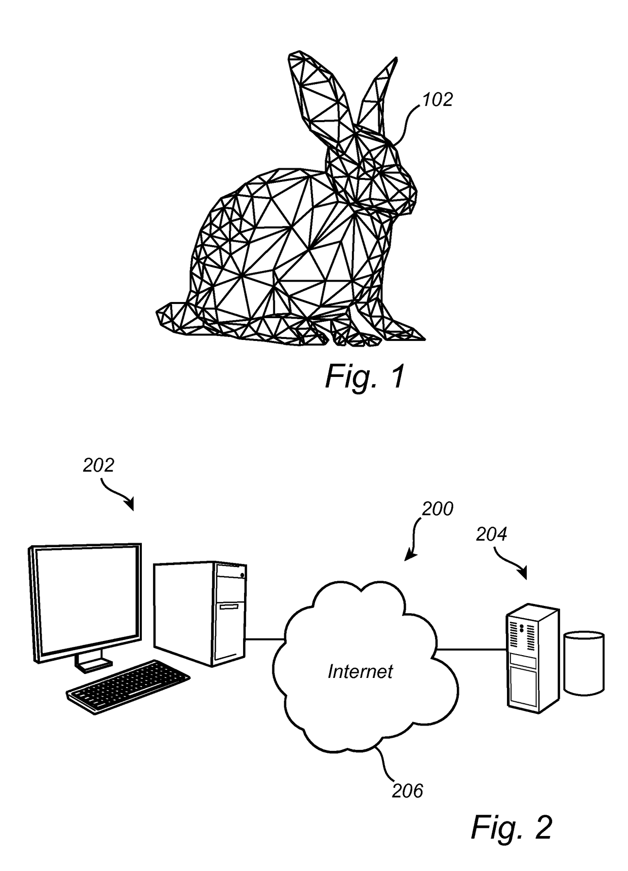
[0036]The process of connecting three-dimensional vertices to form a representation of a graphical image may be referred to as creating a polygon mesh. FIG. 1 illustrates an exemplary three-dimensional graphics image, in the form of a “bunny”, which have been tiled into such a polygon mesh. The bunny 102 is here represented by a large plurality of polygons. In a system with a 3D graphics accelerator, an application program generates three-dimensional geometry d...


PUM


Abstract

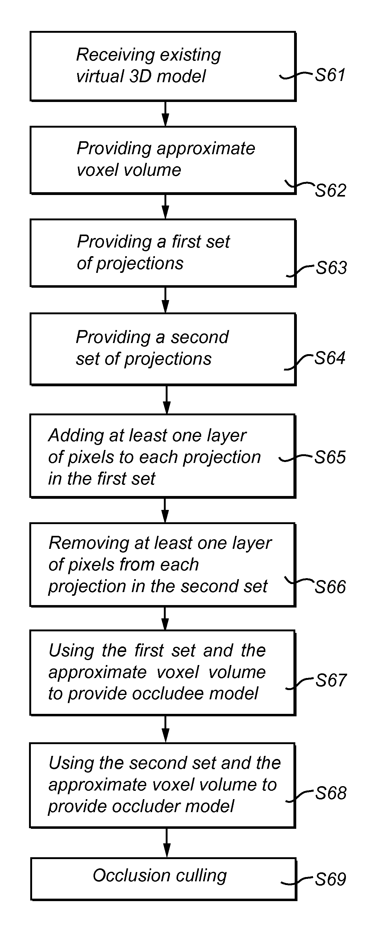
A method and image processing apparatus for creating simplified representations of an existing virtual 3D model for use in occlusion culling. The existing virtual 3D model is received and a visual hull construction is performed on the existing virtual 3D model using an approximate voxel volume consisting of a plurality of voxels, the voxel volume fully encloses the existing virtual 3D model, and a set of projections from a plurality of viewing angles to provide a visual hull of the existing 3D model. The volumetric size of the visual hull of the existing 3D model is increased to envelop the existing virtual 3D model to provide the visual hull as an occludee model, and the volumetric size of the visual hull of the existing 3D model is decreased to be enveloped by the existing virtual 3D model to provide the visual hull as an occluder model. The occludee model and the occluder model are used during runtime in a 3D virtual environment for occlusion culling.The present invention provides simplified representations for occlusion culling in a simple and computationally cost effective manner.

Description

TECHNICAL FIELD[0001]The present invention generally relates to computer graphics and more particularly to a method and system for creating simplified representations of existing virtual 3D models for use in occlusion culling.BACKGROUND OF THE INVENTION[0002]Creation and visualization of computer graphics takes an ever increasing importance in diverse fields of computing such as computer aided design (CAD), architectural walkthroughs, simulations, medical visualization and computer games. The visualization of computer graphics also often requires that interaction with the model takes place at an interactive frequency of greater than 10 frames per second.[0003]A common trend for computer graphics is the increasing amount of complexity and therefore size of the computer graphic models. The initial 3D models are computationally very expensive and thus require specialized graphics systems to handle, furthermore they are generally never able to be handled interactively. The development o...

Claims


Application Information

Patent Timeline
IPC IPC(8): G06T15/40G06T17/20G06T17/00
CPCG06T15/40G06T17/005G06T17/20G06T17/00G06T2210/12G06T7/564G06T15/00G06T17/10
Inventor LINDAHL, ULRIKJOHANSSON, GUSTAF
Owner MICROSOFT TECH LICENSING LLC
Learn More