Rotary electrical machine with improved power electronics

a technology of power electronics and rotary electrical machines, which is applied in the direction of windings, coupling device connections, and association with control/drive circuits, etc., can solve the problems of not being able to achieve and the assembly is not easy to move, and achieve the effect of improving the discharge of hea

Active Publication Date: 2017-12-14
VALEO EQUIP ELECTRIC MOTEUR
View PDF8 Cites 4 Cited by
  • Summary
  • Abstract
  • Description
  • Claims
  • Application Information

AI Technical Summary

Benefits of technology

[0026]According to one embodiment, electrical conductors are positioned between the receipt pins and the components of the regulation module. This makes possible both the power supply to the regulation module, and the interconnection with the

Problems solved by technology

For a stator which has two three-phase systems, i.e. six phases altogether, the present configurations make it necessary to use three power modules, thus constituting a bulky assembly which does not make it possible to adapt to electrical machines with a reduced diameter, or to incorporate

Method used


Image

  • Rotary electrical machine with improved power electronics
  • Rotary electrical machine with improved power electronics
  • Rotary electrical machine with improved power electronics

Examples


first embodiment

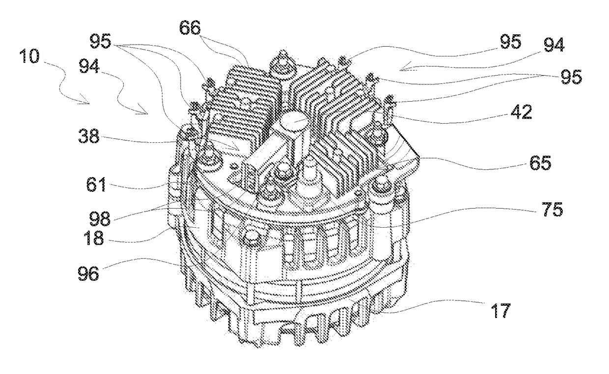
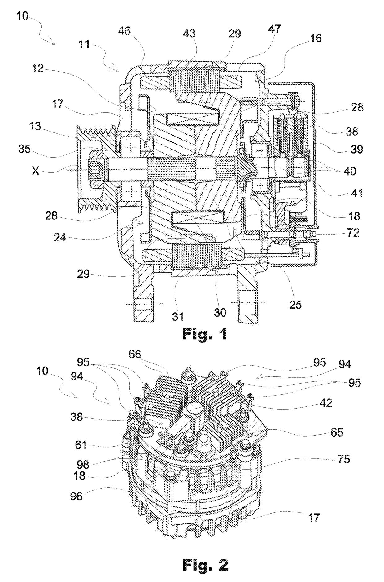
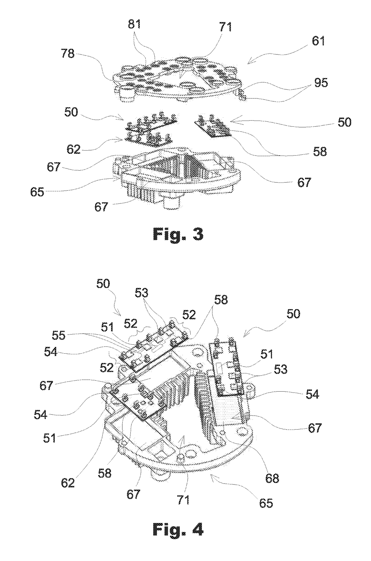
[0072] as can be seen in FIGS. 3, 4, and 5, the power modules 50 as well as the regulation module 62 are integrated in a heat dissipater 65, i.e. they are each positioned inside a corresponding receptacle 67 provided in the heat dissipater 65.

[0073]Preferably, in order to improve the discharge of the heat diffused by the different modules 50 and 62, a layer of thermally conductive adhesive 68 is interposed between the power modules 50 and a base of each corresponding receptacle 67, as well as between the regulation module 62 and a corresponding base of the receptacle 67. Preferably, the layer of adhesive 68 is deposited between the face of the board which does not support any component and the base of the receptacle 67. The adhesive also permits securing of the different modules 50, 62 in the receptacles 67.

[0074]Each receptacle 67 can be filled with a protective layer such as gel or resin, in order to protect the electronic components against the external environment. As a variant,...

second embodiment

[0087] represented in FIGS. 9, 10 and 11, the regulation module 62 is integrated in the connector 61. For this purpose, the connector 61 comprises a cavity 82 for receipt of the regulation module 62. In order to facilitate the assembly between the heat dissipater 65 and the connector 61, the heat dissipater 65 comprises a set-back 85 on its inner face, as shown in FIG. 9. “Inner face” designates the face of the dissipater which is opposite the stator. This set-back 85 has a form which is complementary with the regulation module 62, or more specifically with the projecting walls of the connector 61 which delimits the cavity 82. According to one embodiment, the cavity 82 can be filled with a protective layer such as gel or resin, in order to protect the electronic components against the external environment. As a variant, the cavity 82 can be closed by a cover.

[0088]As can be seen in FIG. 10, receipt pins 86 situated in the extension of the tracks 60 of the connector 61 open into the ...


PUM


Abstract

The invention relates mainly to a rotary electrical machine for a motor vehicle, comprising:
    • a heat dissipater (65);
    • two power modules (50) integrated in the heat dissipater (65), each comprising rectifier elements (53) which form three rectifier bridge arms (52), connection terminals (58) associated with the rectifier bridge arms (52), and a control unit which can control the rectifier bridge arms; and
    • a connector (61) which establishes electrical connections, in particular between the terminals (58) for connection of the power modules (50) and the phase outputs of the rotary electrical machine.

Description

CROSS-REFERENCE TO RELATED APPLICATIONS AND CLAIM TO PRIORITY[0001]This application is related to Patent Application No. 1655517 filed Jun. 14, 2016 in France, the disclosure of which is incorporated herein by reference and to which priority is claimed.FIELD OF THE INVENTION[0002]The present invention relates to a rotary electrical machine with improved power electronics. The invention has a particularly advantageous, but not exclusive, application in the field of alternators for motor vehicles. An alternator of this type transforms mechanical energy into electrical energy, and can be reversible.BACKGROUND OF THE INVENTION[0003]A reversible alternator of this type, known as an alternator-starter, makes it possible to transform electrical energy into mechanical energy, in particular in order to start the thermal engine of the vehicle.[0004]In a known manner, an alternator comprises a housing, and inside the housing, a claw rotor which is integral in rotation with a shaft, and a stato...

Claims


Application Information

Patent Timeline
IPC IPC(8): H02K9/22H01R39/38H02K5/22H01R13/66H02K11/33H02K5/18
CPCH02K9/22H02K11/33H01R13/665H02K5/225H01R39/38H02K5/18H02K11/049H02K9/06H02K11/0094H02K9/227H02K11/05H02K19/365H02K5/148H02K2203/03
Inventor JUGOVIC, SVETISLAVTAUVRON, FABRICEBOUDJEMAI, FAROUKRAGAINE, PIERRE-FRANCOISDE LAMARRE, LAURENTTEMPEZ, HUGUES
Owner VALEO EQUIP ELECTRIC MOTEUR
Why Eureka
Try Eureka