Endodontic apical plug

Active Publication Date: 2017-12-21
AL SHEHRI MOHAMMED
View PDF28 Cites 0 Cited by
  • Summary
  • Abstract
  • Description
  • Claims
  • Application Information

AI Technical Summary

Benefits of technology

[0008]Additionally, these consecutive spaces in the wings increase the flexibility of the carrier and its ability to bend inside the root canal. Also, the upper parts of the lateral annexes of the wings have small rounded angles. This helps the filler or cap reach its final position, even in tortuous canals.
[0009]Also, another advantage is that the length of the cap or filler does not exceed 5 mm from the root apex, which facilitates placing a post in the remaining space in the canal. This solves the problem of having a gripping part in the previous inventions, which obstructs this step. Additionally, there is a place allocated where the needle used in injecting the filling material meets the filler. That makes its exit easier after placing the

Problems solved by technology

Additionally, the driller may change its direction inside the root beca

Method used


Image

  • Endodontic apical plug
  • Endodontic apical plug
  • Endodontic apical plug

Examples


Embodiment Construction

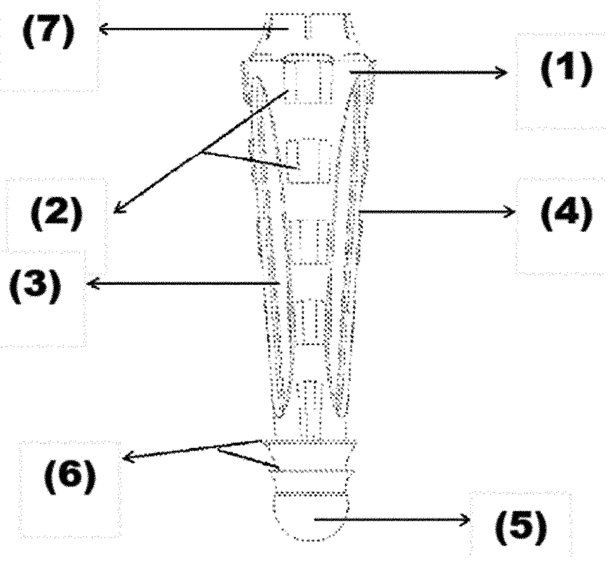
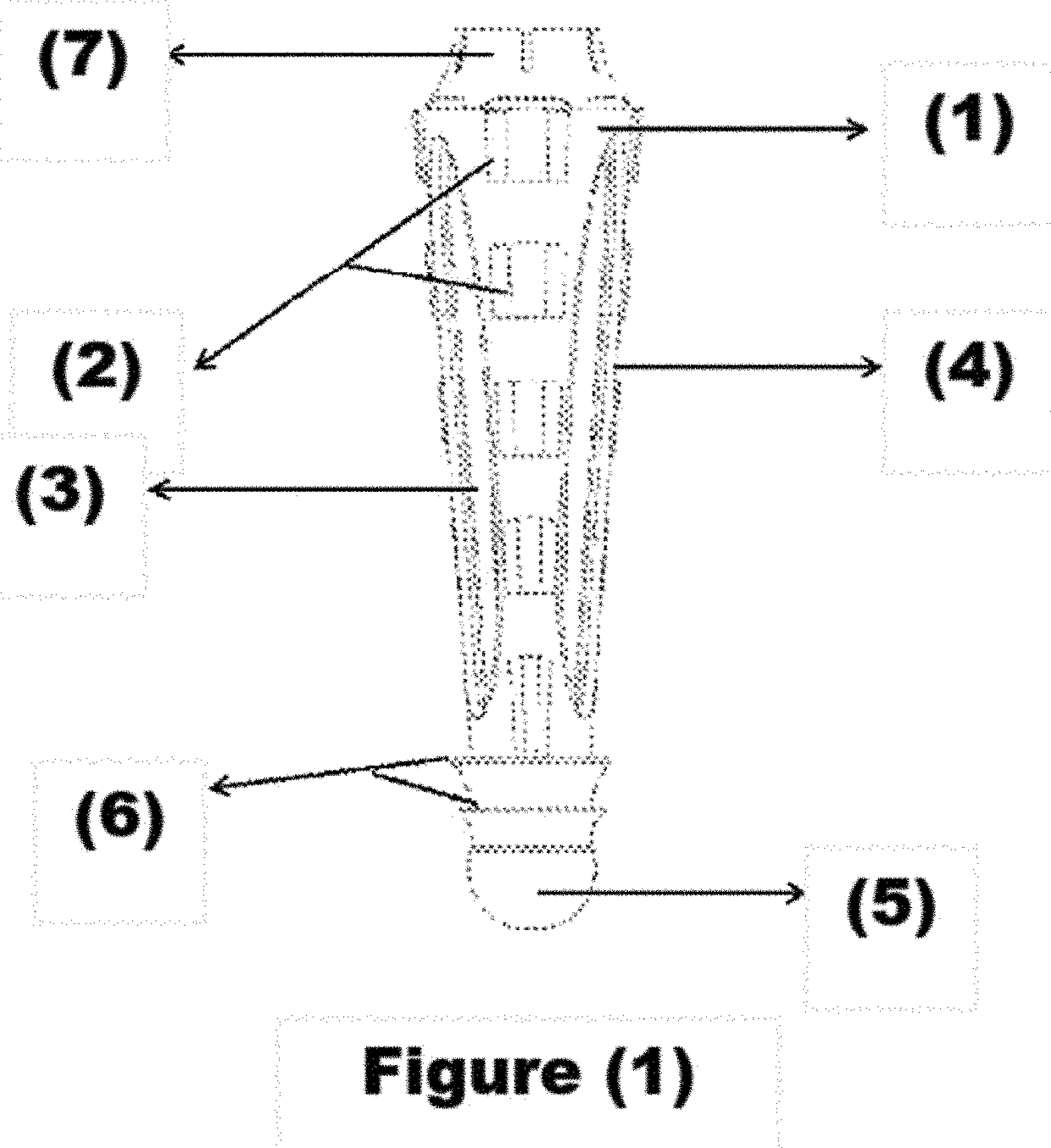
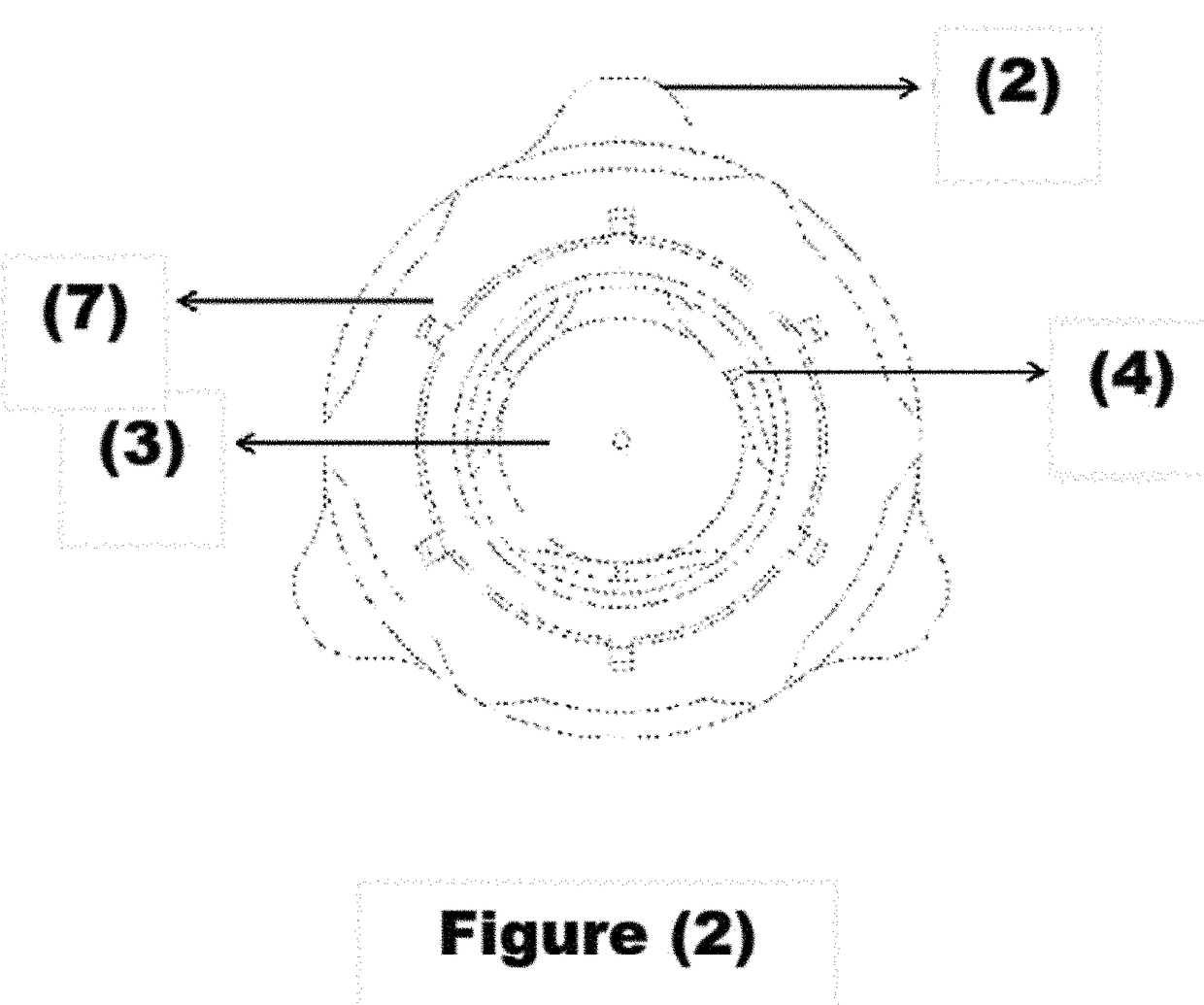
[0016]FIG. 1) illustrates a longitudinal section of the filler used in filling teeth root canals (1) made of plastic (or any other biocompatible material). This filler (1) that measures about 5 mm is placed inside the bottom of the tooth, and the remaining space is filled with filling material known in dentistry. The filler (1) is unique for its elliptical end (5) that allows it to be placed in the desired place, as the elliptical end (5) sets in the tooth apex to prevent leakage of filling material to jaw bones. The filler (1) has lateral openings (4) close to the elliptical end (5). Each opening (4) is linked to the longitudinal cavity (3) that reaches from top of the filler (1) (the opposite end of the elliptical end (5)) to the openings (3).

[0017]The filler (1) is linked from the outside to guiding wings (2) with consecutively discontinuous spaces that separate each wing into several protrusions, which helps the flow of the filling material into the filler (1) and better fill th...


PUM


Abstract

The invention relates to a tool for filling root canals of teeth in order to prevent bacteria passing thereinto following removal of the nerve from the tooth and preparation of the canal for root filling. Owing to the importance of this remedial action, several methods and tools have been developed to facilitate root canal obturation by injection of a leak-proof material. The present invention discloses a plug made from plastic or any other biocompatible material, comprising: a central, conical, cylindrical, longitudinal cavity; lateral elliptical openings connected to said longitudinal cavity; discontinuous lateral guiding supports having rounded angles and spaces therebetween; and a double leak-proof cap. The plug does not require a gripping part, which facilitates the placement of a post inside the root in order to support fixed prosthodontics and to prevent leakage of the obturating material injected into the tooth.

Description

INVENTION BACKGROUND[0001]This invention is related to a tooth canal filler used for filling tooth root canals after extracting the nerve and preparing the canal for a final root filling status.[0002]There are several previous experiments and inventions that have existed to achieve this goal, including Thermafil®, a canal filling method with European patent No. EP 1001728 B1. It requires heating the canal filler in advance prior to putting it in the canal in order to be mild. This causes an increase in tissue temperature to an extent that could harm it. Additionally, the material coating the filler may separate from it during the insertion process, which may harm the distribution of the leak-proof material inside the root canal; in addition to the problem arising from the need to remove the gripping part after the clinical procedure is performed.[0003]EU patent application No. EP 2015109 A1 presented another canal filler. The problem with this system is that the leak-proof material ...

Claims


Application Information

Patent Timeline
IPC IPC(8): A61C5/50
CPCA61C5/50A61C5/55
Inventor AL SHEHRI, MOHAMMED
Owner AL SHEHRI MOHAMMED
Why Eureka
Try Eureka