Run-through cleaning device and cleaning method therefor

a cleaning device and run-through technology, applied in the direction of cleaning using liquids, house cleaners, tableware washing/rinsing machines, etc., can solve the problems of affecting the cleaning effect, and the inability to guarantee the complete cleaning, so as to reduce the pressure or vacuum, improve the removal of contaminants, and reduce the maintenance effort

Inactive Publication Date: 2017-12-21
OSSBERGER GMBH CO
View PDF2 Cites 6 Cited by
  • Summary
  • Abstract
  • Description
  • Claims
  • Application Information

AI Technical Summary

Benefits of technology

[0013]A further advantage of the present invention is that the bulk parts are moved through the channel in a forced advance. This is realized without a conveyor device moving through the channel. As the conveyor device supports the transporting and maintaining of contaminants, it has been specifically avoided. For allowing, however, at the used forced advance also the access to and the cleaning of the front ends of adjacent mutually abutting bulk parts, the channel interior is qualified by an at least partly curvilinear course of the cleaning path of the bulk parts. This means that the bulk parts move not solely straight or in unchanged orientation of adjacent bulk parts with respect to each other through the run-through cleaning device. As they follow the curvature of the cleaning path defined by the channel interior, at least at specific positions or in specific portions of the cleaning path in the channel interior, the mutual abutment of adjacent bulk parts is reduced at the front ends preferably to a punctual abutment to further transmit the advance force between the bulk parts. If a preferred front end abutment of the bulk parts changes from an areal abutment to a punctual abutment, the remaining of the front end is accessible for one or several cleaning media. The punctual abutment is further preferred by means of the not straight forced guiding in the channel interior such that all surfaces and geometry features of the bulk parts are accessible for the media. The cleaning media removes then the contaminants being present there so that at the end of the channel segment or at the end of a plurality of subsequently arranged channel segments a cleaned bulk part is present. As it is described in detail below, curvatures of the cleaning path are achieved by chicanes protruding into the channel interior or by a curvilinear course of the channel interior itself
[0014]Further, it was identified as advantageous to use besides or instead of air as cleaning media also other media, preferably liquids, as cleaning media. Thus, it is preferred to use several cleaning media or air and at least one cleaning liquid or another solvent, like preferably CO2, as cleaning media in combination to improve the removal of contaminants from the surface of the bulk parts. For example, CO2 as solvent is used in a semi-liquid state. It is also advantageous to use an ionized gaseous medium as cleaning medium. In this way, for example plastic particles adhering to charged surfaces of the bulk part to be cleaned are detachable. An ionization of the gaseous medium like air is performed by guiding the medium through inductors. Advantageously, the supply of an ionized gaseous medium is performed especially by means of an ionization nozzle. Further, the usage of liquids serves preferably for rinsing the channel segments provided for a sole air cleaning by means of the liquid. This realizes the preferred self-cleaning of the run-through cleaning device.
[0015]According to a preferred embodiment of the inventive run-through cleaning device, the at least one channel segment is fastened and replaceable or exchangeable by means of a quick release system. This construction ensures a fast and only with a small maintenance effort realizable individual adaptation of a run-through cleaning device to a new geometry of a bulk part. Further, it is possible to detect defective channel segments without effort (inspection) and to replace them, if necessary. A further advantage is that one can react flexibly to cleaning deficiencies or any other necessity for changing the cleaning path.
[0016]According to a further preferred embodiment of the present invention, the air supply conduits are connected to a surroun...

Problems solved by technology

After the production of multi-bulk parts, as for example turning parts for ball bearings, pellets, connection elements and the like, the surfaces thereof are contaminated among others with chippings due to the machining, lubricants and/or coolants as well as possibly with oil.
The outer circumferential surfaces of the bulk parts are cleaned by this cleaning device but, however, due to the forced advance, the front ends of the...

Method used


Image

  • Run-through cleaning device and cleaning method therefor
  • Run-through cleaning device and cleaning method therefor
  • Run-through cleaning device and cleaning method therefor

Examples


Embodiment Construction

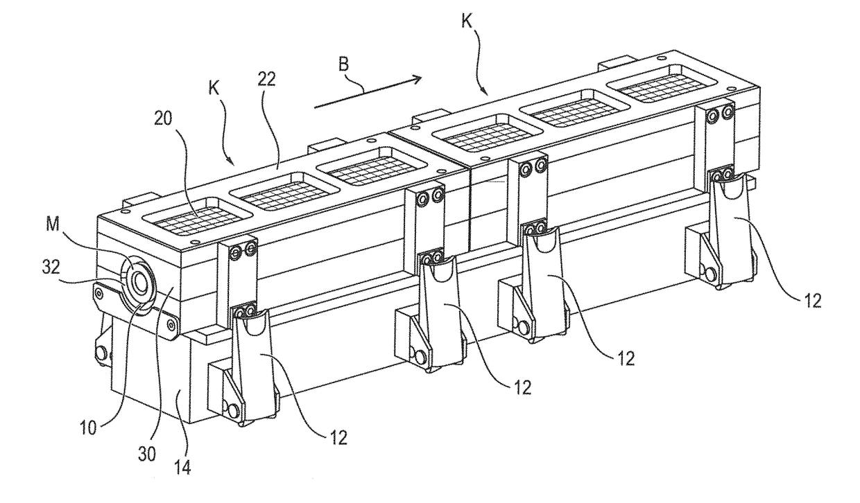
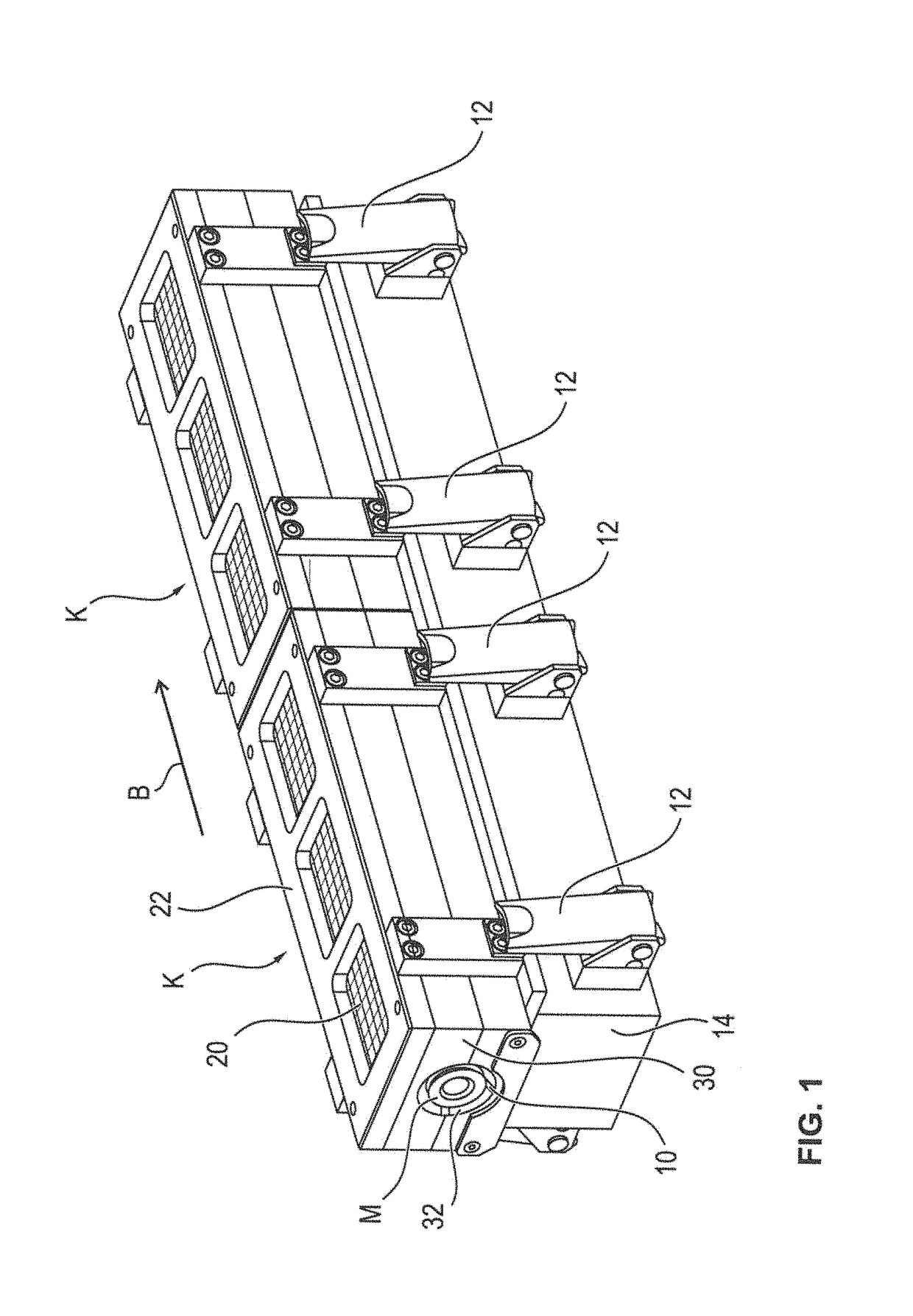
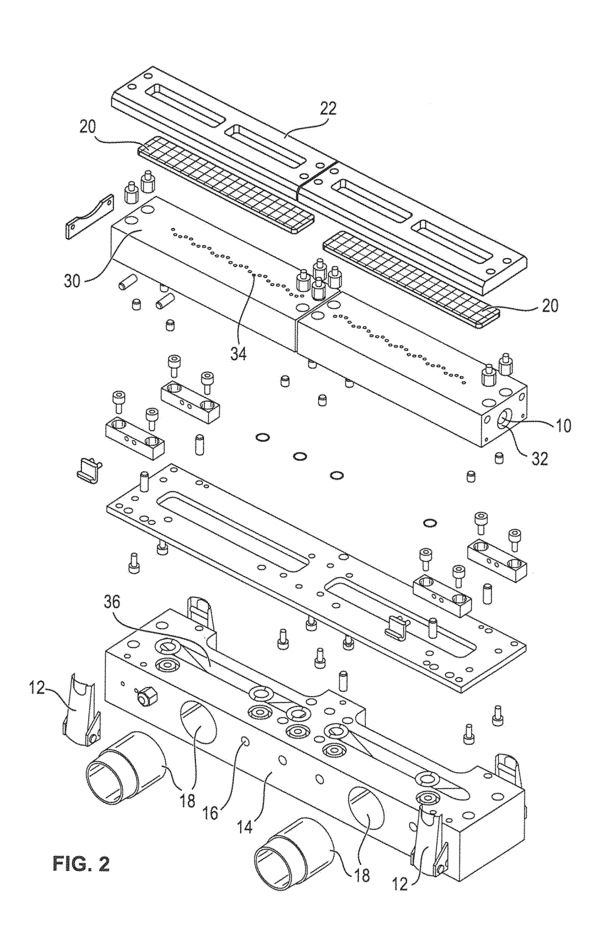
[0067]The inventive run-through cleaning device comprises at least a modular tunnel-like channel segment K. A combination of two preferred channel segments K is shown in FIG. 1. FIG. 2 shows an exploded view of a further preferred embodiment of the modular channel segment K. In the run-through cleaning device, a plurality of bulk parts M is moved in a movement direction B through a channel interior 10 of at least one modular channel segment K. For this purpose, the bulk parts M are arranged in a row in succession. A conveyor device (not shown) is arranged outside of the channel interior 10 and moves the bulk parts M in mutual abutment of adjacent bulk parts M through the channel interior 10. Thus, the bulk parts M are moved by means of a forced advance. The forced advance ensures that the conveyor device is arranged outside of the channel interior 10. Thereby, no dragging of cleaning media or of the contaminants removed from the bulk parts M occurs within the channel interior 10 by ...


PUM


Abstract

A run-through cleaning device for bulk parts as well as a cleaning method therefor. Within the run-through cleaning device, the bulk parts are moved by means of a forced advance. By means of chicanes and/or a curvilinear course of the channel interior, the mutually abutting front ends of adjacent bulk parts are made accessible. Due to this arrangement, it is possible to also clean the front ends.

Description

CROSS REFERENCE TO RELATED APPLICATIONS[0001]Pursuant to relevant portions of 35 U.S.C. §119, this application claims the priority of German Patent Application No. DE 10 2016 111 050.7, filed on Jun. 16, 2016 and European Patent Application No. EP 17 173 583.0, filed on May 30, 2017. The entire content of the priority applications is incorporated herein by reference in their entirety.Field of the Invention[0002]The present invention is related to a run-through cleaning device for bulk parts which come for example from a machining or processing machine, like screws, pellets, turned parts or the like, as well as a cleaning method of such bulk parts, which is realized by means of the run-through cleaning device.Background of the Invention[0003]After the production of multi-bulk parts, as for example turning parts for ball bearings, pellets, connection elements and the like, the surfaces thereof are contaminated among others with chippings due to the machining, lubricants and / or coolant...

Claims


Application Information

Patent Timeline
IPC IPC(8): B08B3/04A47L15/24B05B1/00B08B3/02B65G45/22
CPCB08B3/042A47L15/248B05B1/005B08B3/022B65G45/22B08B5/023
Inventor HUETTINGER, MARKUSOSSBERGER, KARL-FRIEDRICH
Owner OSSBERGER GMBH CO
Why Eureka
Try Eureka