Beverage active chiller

a chiller and active technology, applied in the field of portable chillers, can solve the problems of inflexibility of approaches to accept cans or bottles of different diameters, toxic, and high cost of supply, and achieve the effect of simple and effective solution and avoidance of known devices

Active Publication Date: 2017-12-21
NGUYEN HAI T
View PDF0 Cites 6 Cited by
  • Summary
  • Abstract
  • Description
  • Claims
  • Application Information

AI Technical Summary

Benefits of technology

[0007]Further investigation shows a known device for chilling a beverage object comprises a plurality of chilling members. The disadvantage of this invention is that each chilling member must be placed in a pouch like carrier in order to form a hollow cylindrical shape. Thus, the chilling members do not have direct contact with the beverage object, resulting in a less effective thermal energy transfer. The second disadvantage of the invention is the required wrapping like of the pouch carrier to form a hollow cylindrical shape. This technique will not result in a true cylindrical shape due to the variant in the diameter of different sizes of cans or bottles. Another disadvantage is not all chilling members are in contact with the beverage object which results in a lost effectiveness for all chilling members. Such a device is known by U.S. Patent Application Publication US 2006 / 0242990 A1.
[0008]It is the object of this invention to provide a new and improved device for chilling a beverage object in which the disadvantages of the known devices have been avoided.
[0009]The present invention provides a simple and effective solution to chill a beverage object for an extended length of time under ambient condition. For purposes of this application, the term “beverage” is used to refer to consumable substances of all types and phases, including by way of illustration only and not limitation, soft drinks, alcoholic beverages, water and the like. It is also understood that, for purposes of this application, the term “object” is used to refer to containers and receptacles of all types, materials and design constructions, including by way of illustration only and not limited to cans, bottles, cups, glasses and the like.
[0010]The apparatus of the present invention is comprised of a generally main portion of a cup like structure capable of receiving other components of the said invention and including a beverage object within. A removable chiller in the form of a cylindrical sleeve is variably expandable, contractible and fits within the main body portion of the apparatus to provide a means by which to produce and maintain desired chill condition for an extended period of time to a beverage object; while being exposed to ambient temperature condition. A sealable cap of ring like structure with built-in elastic material capable of expansion and retraction to its original state, when placed over the beverage object and capped onto main body portion, providing further protection, insulation and preserving pre-chilled temperature of the beverage object and the frozen condition of the chiller. A “raiser” is an added optional component to raise the height of shorter beverage object, thus allowing the full use of the embodiment.
[0011]To the accomplishments of the above, this invention may be embodied in the form illustrated in the accompanying drawings, attention being called to the fact, however, that the drawings are illustrative only, and that changes may be made in the specific construction illustrated and described within the scope of the appended claims.

Problems solved by technology

Whereas, this approach does not have the flexibility to accept variety of cans or bottles of different diameters.
The annular space is a clear disadvantage because it does not allow for the maximum thermal energy transfer to the beverage object.
First, the use of non-freezing cooling liquid is not as effective as solid ice for thermal energy, it is considered toxic and costs more to supply.
The inherently unpredictable shape of the compartments and the expansion and contraction of the sleeve do not fully accommodate the can or bottle.
Furthermore, each compartment with two sub-compartments and the required use of exotic materials for construction are not a good economic factor.
Lastly, by relying on the outer compartment for providing insulation to the cooling device is inadequate due to partial direct exposure of the inner compartment to ambient condition.
The disadvantage is if the coolant fluid is non-freezing; then it will not have maximum thermal energy like frozen ice.
The second disadvantage; the plurality removable plastic pouch does not allows for quick and instant ability to form the hollow cylindrical shape.
The disadvantage of this invention is that each chilling member must be placed in a pouch like carrier in order to form a hollow cylindrical shape.
Thus, the chilling members do not have direct contact with the beverage object, resulting in a less effective thermal energy transfer.
The second disadvantage of the invention is the required wrapping like of the pouch carrier to form a hollow cylindrical shape.
This technique will not result in a true cylindrical shape due to the variant in the diameter of different sizes of cans or bottles.
Another disadvantage is not all chilling members are in contact with the beverage object which results in a lost effectiveness for all chilling members.

Method used


Image

  • Beverage active chiller
  • Beverage active chiller
  • Beverage active chiller

Examples


Embodiment Construction

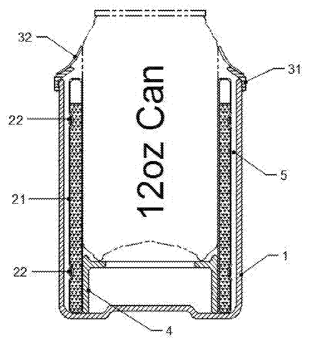
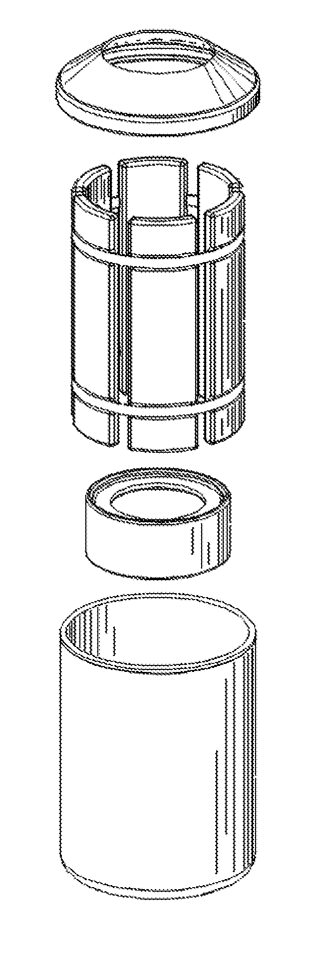
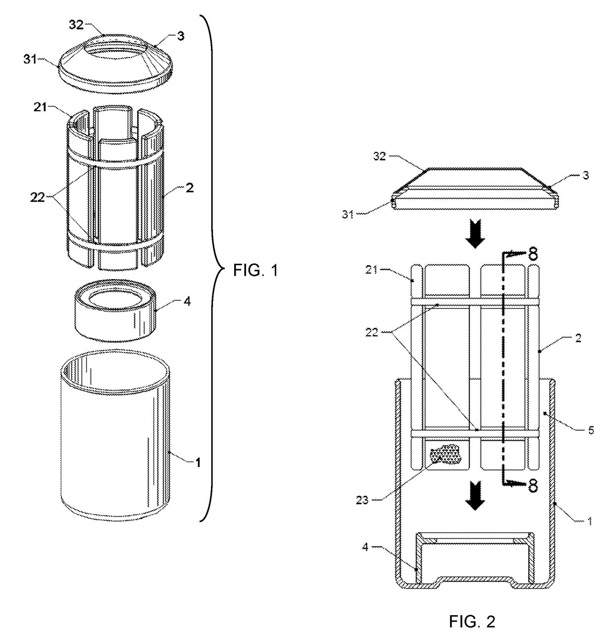
[0020]Referring to FIG. 1, there is shown an embodiment of an apparatus of the present invention. In the preferred embodiment, the apparatus comprises a main body portion 1, a removable cylindrical sleeve 2, a sealable cap 3, and a raiser 4.

[0021]The main body portion 1 is a cup like configuration designed to receive the removable cylindrical sleeve 2, a raiser 4 (optional), a sealable cap 3, and an object to be chilled (FIGS. 5-7). The main body portion 1 is preferably constructed singularly of thermoplastic resins such as Polycarbonate, ABS, LDPE, or HDPE etc. All depended, but not limited to, on the desired strength, durability, cosmetically, availability and cost factor. It is further noted that the main body portion 1 also be made of metals such as Aluminum, Stainless Steel, Titanium etc. for high end market. With metal construction, there should be consideration of a rubber or thermoplastic layer on the interior wall of main body portion 1 to insulate / shield the high thermo co...


PUM


Abstract

A mechanical apparatus comprised of a plurality of pods in the form of a cylindrical sleeve, containing liquid, to be frozen for the purpose of dynamically transfer / impart its charged thermal energy to a directly contacted object placed within. The pods are joined to each other by elastic bands allowing it to instantly expanse and grip varying size beverage containers. Furthermore, the plurality of pods and a beverage container are disposed in an insulated holder; a sealable cap is then inserted to seal off and insulate the discharging of thermal energy therein from ambient conditions. A beverage in the form of can or bottle may be placed in the apparatus to achieve desired chill temperature for an extended length of time in high ambient temperature conditions.

Description

CROSS REFERENCE TO RELATED PROVISIONAL APPLICATION[0001]This application is a conversion to a nonprovisional under 37 C.F.R. §1.53 (c)(3) of U.S. provisional application No. 62 / 315,191, entitled “ Beverage Chilling Pod Sleeve”, filed on Mar. 30, 2016, by inventor Hai T. Nguyen.BACKGROUND OF THE INVENTION[0002]Often times, such as a backyard gathering, an outdoor event, picnicking, camping and boating etc., whereas, the outdoor temperature is usually much warmer than the temperature of controlled indoor setting; a chilled canned or bottled beverage will not be able to maintain its original chilled status for a length of time, especially in boating activities. After about 15 minutes of direct exposure to an elevated ambient temperature; the temperature of a chilled beverage becomes warm and continues to be warmer over time to a state that the beverage may not be as desirable for consumption. Alcoholic drinks such as beer and white wine; refreshment drinks such as soda, juice and water...

Claims


Application Information

Patent Timeline
Patent Type & Authority Applications(United States)
IPC IPC(8): F25D3/08
CPCF25D3/08F25D2303/08221F25D2303/08222F25D2331/803F25D2500/02F25D2331/808F25D2303/0841F25D2303/0843F25D2331/805F25D2331/809
Inventor NGUYEN, HAI T.
Owner NGUYEN HAI T
Why Eureka
Try Eureka