
Radar apparatus and method for processing radar signal

a radar and apparatus technology, applied in the direction of instruments, polarised antenna unit combinations, antennas, etc., can solve the problems of reducing the space for antenna implementation and difficult to reduce the size of hardware, and achieve the effect of reducing the size of the radar apparatus

Active Publication Date: 2017-12-21
HL KLEMOVE CORP
View PDF1 Cites 16 Cited by
  • Summary
  • Abstract
  • Description
  • Claims
  • Application Information

AI Technical Summary

Benefits of technology

The present patent suggests a way to make a radar for vehicles smaller while maintaining its performance. This is done by reducing the number of reception chips in the radar and keeping the number of channels at a certain level. This technique ensures that the antenna works well. Overall, this results in a smaller radar for vehicles while still providing the same level of performance.

Problems solved by technology

However, in the case of a radar apparatus for a vehicle, as the size of the radar is reduced, an antenna implementing space is downsized and interference problem may be caused due to antenna output implementation and transmission and reception in a proximity space.
Therefore, even though the radar apparatus for a vehicle of the related art is required to reduce the size of the radar apparatus, it is difficult to reduce the size of the hardware in order to configure a predetermined number of channels to ensure the performance of the radar.

Method used


Image

  • Radar apparatus and method for processing radar signal
  • Radar apparatus and method for processing radar signal
  • Radar apparatus and method for processing radar signal

Examples


Embodiment Construction

[0026]Hereinafter, some exemplary embodiments of the present disclosure will be described in detail with reference to the accompanying drawings. When reference numerals denote components in the drawings, even though the like components are illustrated in different drawings, it should be understood that like reference numerals refer to the same components. Furthermore, when it is judged that specific description on known configurations or functions related in the description of the present disclosure may unnecessarily obscure the essentials of the present disclosure, the detailed description will be omitted.

[0027]Further, some exemplary embodiments of the present disclosure will be described in detail with reference to the accompanying drawings. In describing components of the exemplary embodiment of the present disclosure, terminologies such as first, second, A, B, (a), (b), and the like may be used. However, such terminologies are used only to distinguish a component from another c...


PUM


Abstract

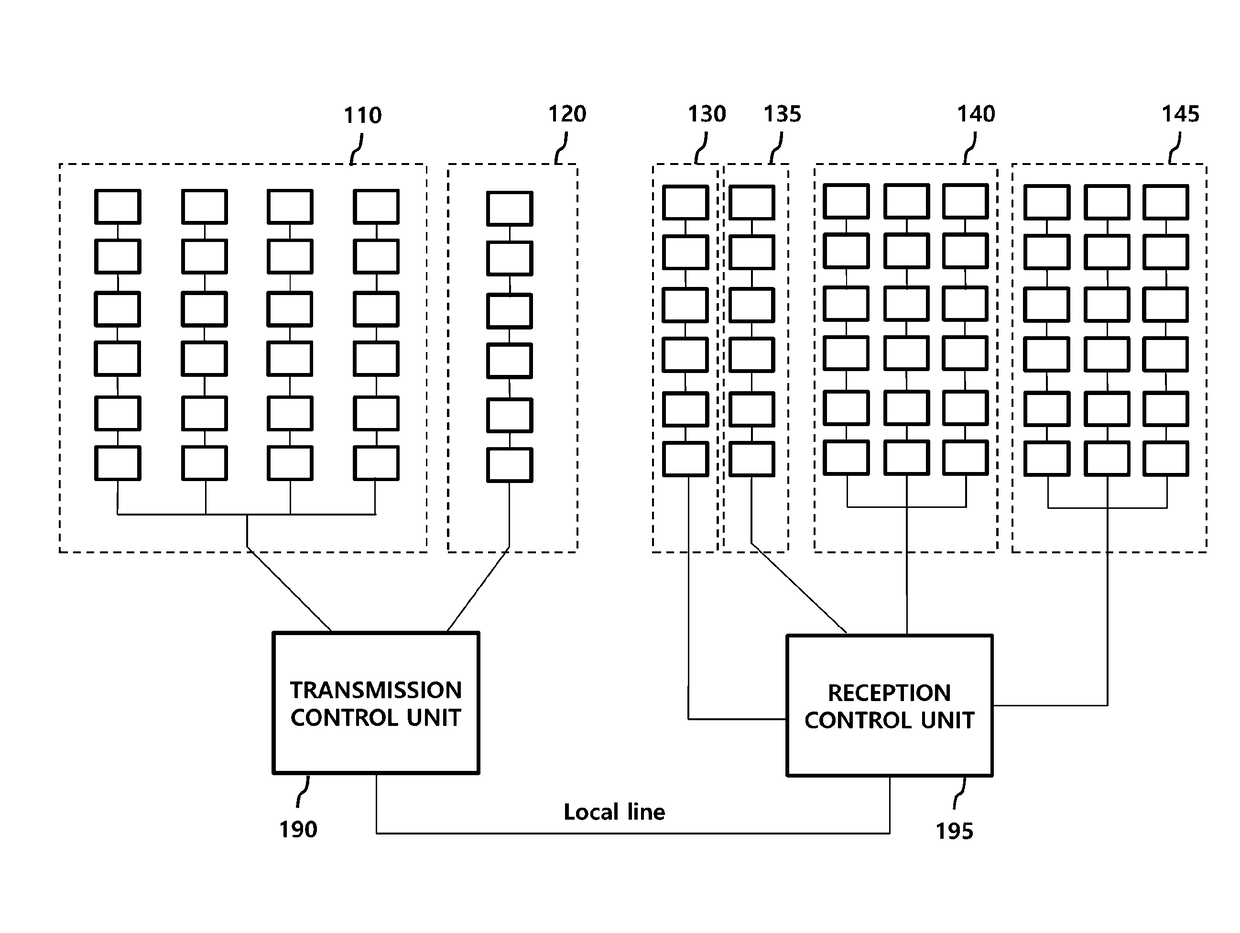
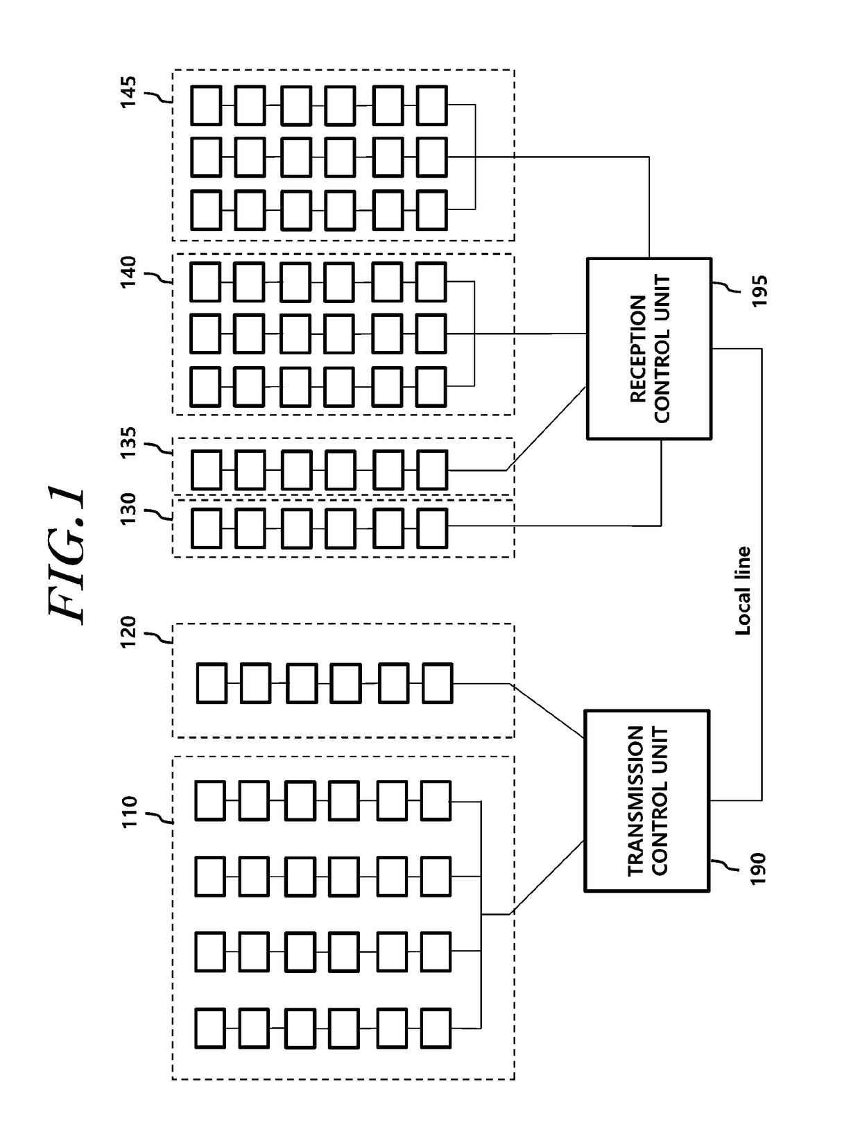
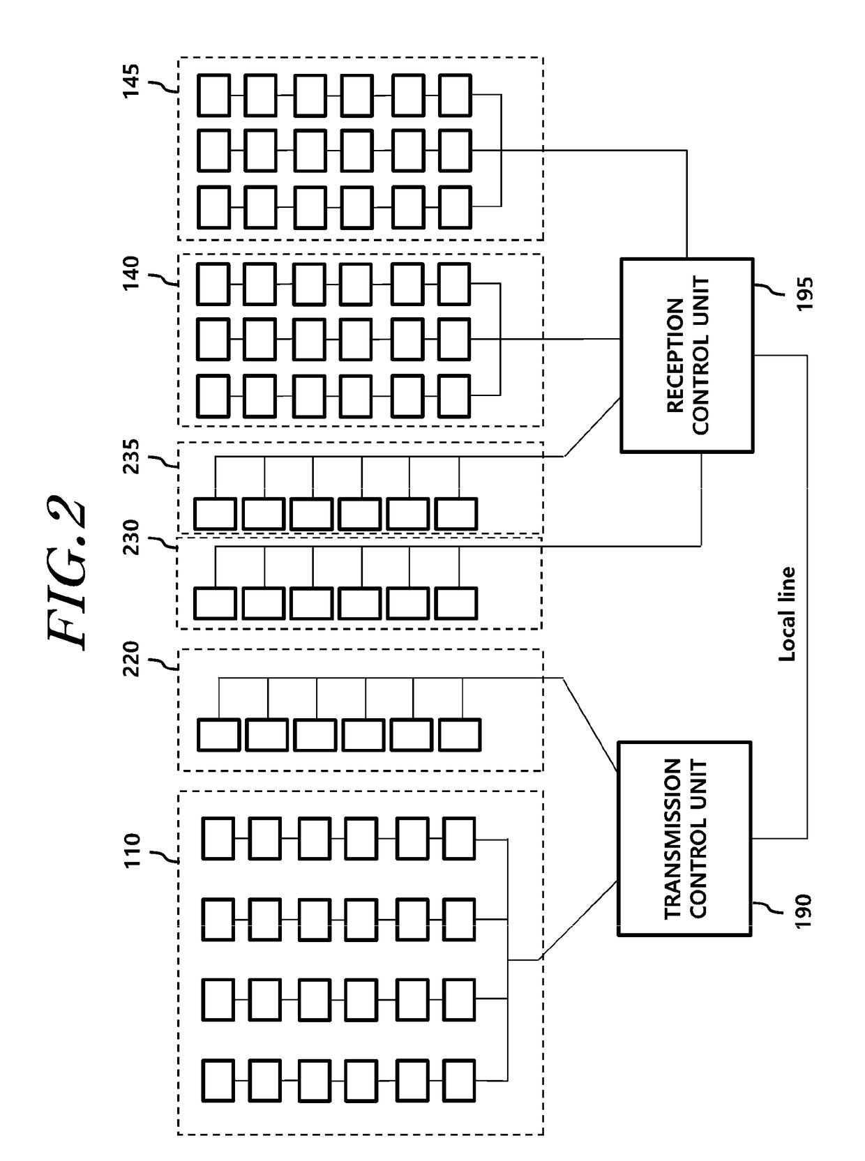
The present disclosure relates to a radar apparatus and a method for processing a signal using a radar apparatus, and more particularly, to an apparatus and a method for receiving and processing reception signals having different polarization characteristics using one array antenna. Specifically, the present disclosure provides a radar apparatus including: a long-range transmission antenna unit including one or more long-range transmission array antennae which transmit a first polarized transmission signal; a short-range transmission antenna unit including one or more short-range transmission array antennae which transmit a second polarized transmission signal; a complex array antenna unit which includes one or more complex array antennae receiving a first polarized reception signal and a second polarized reception signal which are received by reflecting the first polarized transmission signal and the second polarized transmission signal from a target; and a signal processing unit which detects the target using the first polarized reception signal and the second polarized reception signal, in which the first polarized reception signal has a cross polarization characteristic with respect to the second polarized reception signal, and a radar signal processing method.

Description

CROSS-REFERENCE TO RELATED APPLICATIONS[0001]This application claims priority from Korean Patent Application No. 10-2016-0076250, filed on Jun. 20, 2016, which is hereby incorporated by reference for all purposes as if fully set forth herein.BACKGROUND OF THE INVENTIONField of the Invention[0002]The present disclosure relates to a radar apparatus and a method for processing a signal using a radar apparatus, and more particularly, to an apparatus and a method for receiving and processing reception signals having different polarization characteristics using one array antenna.Description of the Related Art[0003]A radar technology refers to a technology which detects a target using a reception signal which is received by reflecting a signal transmitted by a transmission antenna of radar apparatus from a target and obtains information on the target.[0004]Such a radar technology is being used in various fields such as a vehicle, an aircraft, or a military purpose. Specifically, a radar ap...

Claims


Application Information

Patent Timeline
Patent Type & Authority Applications(United States)
IPC IPC(8): G01S7/02H01Q15/14H01Q21/00H01Q21/24G01S13/931
CPCG01S7/024H01Q15/14H01Q21/245H01Q21/0075G01S7/02G01S7/023G01S7/411G01S7/03G01S13/931H01Q1/3233H01Q25/001H01Q21/24H01Q13/08
Inventor KIM, SU HAN
Owner HL KLEMOVE CORP
Learn More