Lens drive device, camera module, and camera-mounting device

a technology of lens drive and camera module, which is applied in the direction of optical radiation measurement, instruments, television systems, etc., can solve the problems of long time period until capturing and focus takes time, and achieve the effect of not increasing the cost of components or complicating assembly work

Active Publication Date: 2017-12-21
MITSUMI ELECTRIC CO LTD
View PDF3 Cites 8 Cited by
  • Summary
  • Abstract
  • Description
  • Claims
  • Application Information

AI Technical Summary

Benefits of technology

[0012]According to the present invention, a part of a member that is displaced together with the AF movable part is utilized as the reflection plate, and thus the reflection-type photo reflector can be mounted without increasing the component cost or complicating the assembly work. Accordingly, the present invention is useful for the case where automatic focusing is performed with a closed loop control system using the reflection-type photo reflector.

Problems solved by technology

With such a method, however, focusing takes time, and the time period until capturing is long.

Method used


Image

  • Lens drive device, camera module, and camera-mounting device
  • Lens drive device, camera module, and camera-mounting device
  • Lens drive device, camera module, and camera-mounting device

Examples


Embodiment Construction

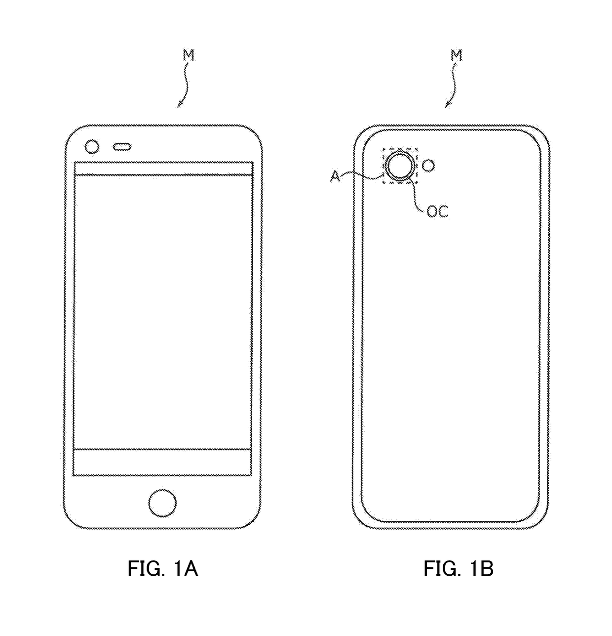
[0022]In the following, an embodiment of the present invention is described in detail with reference to the drawings. FIGS. 1A and 1B illustrate smartphone M (camera mounting device) in which camera module A according to the embodiment of the present invention is mounted. FIG. 1A is a front view of smartphone M, and FIG. 1B is a rear view of smartphone M.

[0023]For example, smartphone M is provided with camera module A as a back side camera OC. Camera module A has an auto focus function, and performs automatic focusing at the time of capturing a subject.

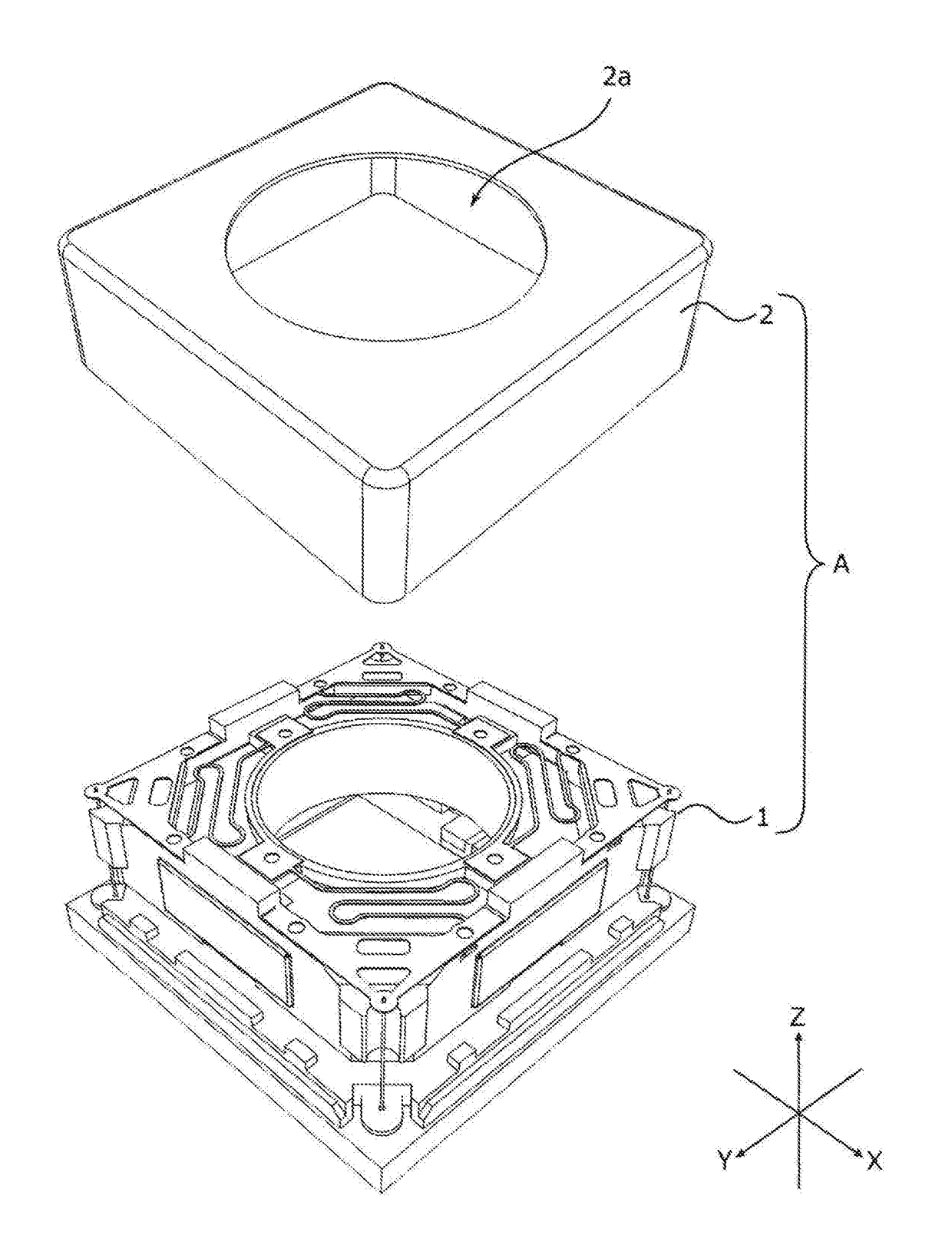
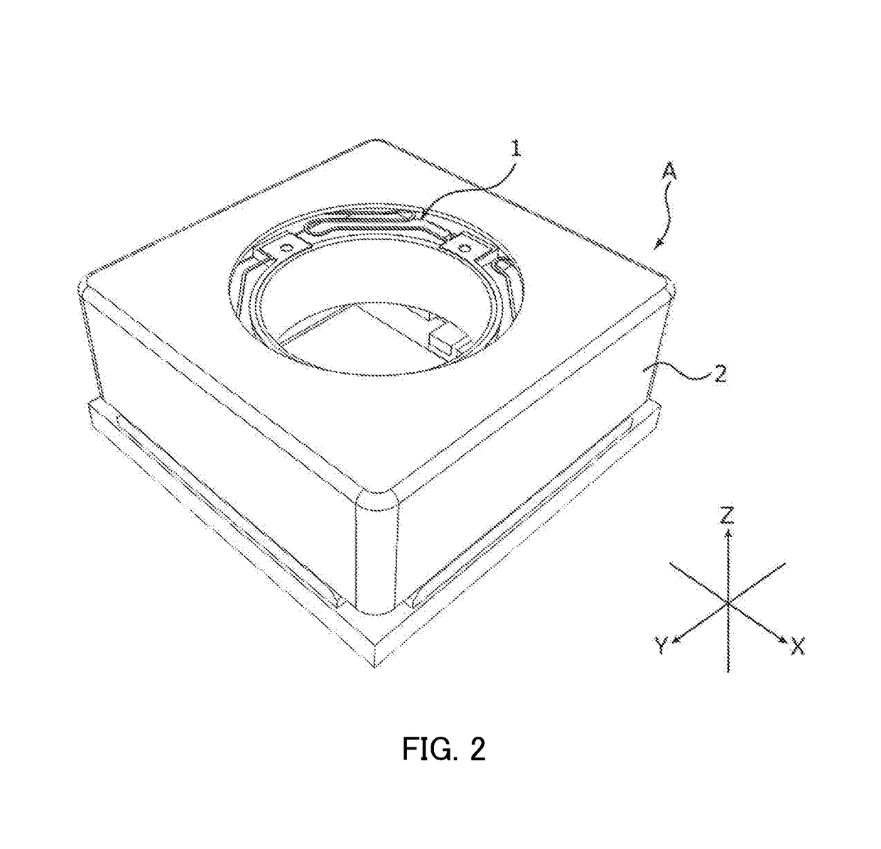
[0024]FIG. 2 is a perspective view of an external appearance of camera module A. FIG. 3 is an exploded perspective view of camera module A. As illustrated in FIG. 2 and FIG. 3, descriptions will be made with an orthogonal coordinate system (X, Y, Z) in the present embodiment. Also in the drawings described later, descriptions will be made with an orthogonal coordinate system (X, Y, Z). Camera module A is mounted such that the vertical...


PUM


Abstract

Provided is a lens drive device that, using drive force from a voice coil motor, automatically carries out focusing by moving an autofocus movable unit with respect to an autofocus fixed unit in the direction of an optical axis. The lens drive unit is provided with a position detection unit that is disposed with an intervening space on the image formation side of the autofocus movable unit in the direction of the optical axis and that is for emitting light toward the autofocus movable unit, receiving reflected light that has been reflected by the autofocus movable unit, and detecting the position of the autofocus movable unit in the direction of the optical axis on the basis of the received light intensity. Part of the member displaced along with the autofocus movable unit functions as a reflective plate for reflecting light emitted from the position detection unit.

Description

TECHNICAL FIELD[0001]The present invention relates to an auto-focusing lens driving device, a camera module having an auto-focusing function, and a camera mounting device.BACKGROUND ART[0002]In general, a small-sized camera module is mounted in mobile terminals such as a smartphone. In such a camera module, a lens driving device having an auto-focusing function (hereinafter referred to as “AF (Auto Focus) function”) of automatically performing focusing at the time of capturing a subject is applied.[0003]An auto-focusing lens driving device includes an auto-focusing driving part (hereinafter referred to as “AF driving part”) for moving the lens part in the light axis direction. The AF driving part includes, for example, an auto-focusing coil part (hereinafter referred to as “AF coil part”) disposed around the lens part, and an auto-focusing magnet part (hereinafter referred to as “AF magnet part”) disposed separately from the AF coil part in the radial direction. An auto-focusing mov...

Claims


Application Information

Patent Timeline
Patent Type & Authority Applications(United States)
IPC IPC(8): G02B7/10G02B7/28G02B7/09H04N5/232G01J1/04
CPCG02B7/102G02B7/09H04N5/232G01J1/0414G02B7/28G02B26/085H04N23/56H04N23/55H04N23/54H04N23/60G02B7/08H04N23/57
Inventor SATO, YOSHIAKIOSAKA, TOMOHIKOKOBAYASHI, NORIYUKIHONMA, TOSHIHIKO
Owner MITSUMI ELECTRIC CO LTD
Why Eureka
Try Eureka