
IMPEDANCE HELICAL ANTENNA FORMING Pi-SHAPED DIRECTIONAL DIAGRAM

a helical antenna and directional diagram technology, applied in the field of helical antennas for use in gps receivers, can solve the problems of not providing the required directional diagram drop, different shape,

Active Publication Date: 2017-12-21
TOPCON POSITIONING SYST INC
View PDF3 Cites 0 Cited by
  • Summary
  • Abstract
  • Description
  • Claims
  • Application Information

AI Technical Summary

Benefits of technology

The proposed antenna design achieves a Down / Up ratio of at least −20 dB at elevations above 10 degrees, effectively suppressing ground-reflected signals and enhancing GPS positioning accuracy.

Problems solved by technology

Note that the antenna in U.S. Pat. No. 6,407,720 can operate at GPS frequencies with scaling, but the directional diagram's shape will be different and will not provide the required directional diagram drop at angles close to horizon.

Method used


Image

  • IMPEDANCE HELICAL ANTENNA FORMING Pi-SHAPED DIRECTIONAL DIAGRAM
  • IMPEDANCE HELICAL ANTENNA FORMING Pi-SHAPED DIRECTIONAL DIAGRAM
  • IMPEDANCE HELICAL ANTENNA FORMING Pi-SHAPED DIRECTIONAL DIAGRAM

Examples


Embodiment Construction

[0029]Reference will now be made in detail to the preferred embodiments of the present invention, examples of which are illustrated in the accompanying drawings.

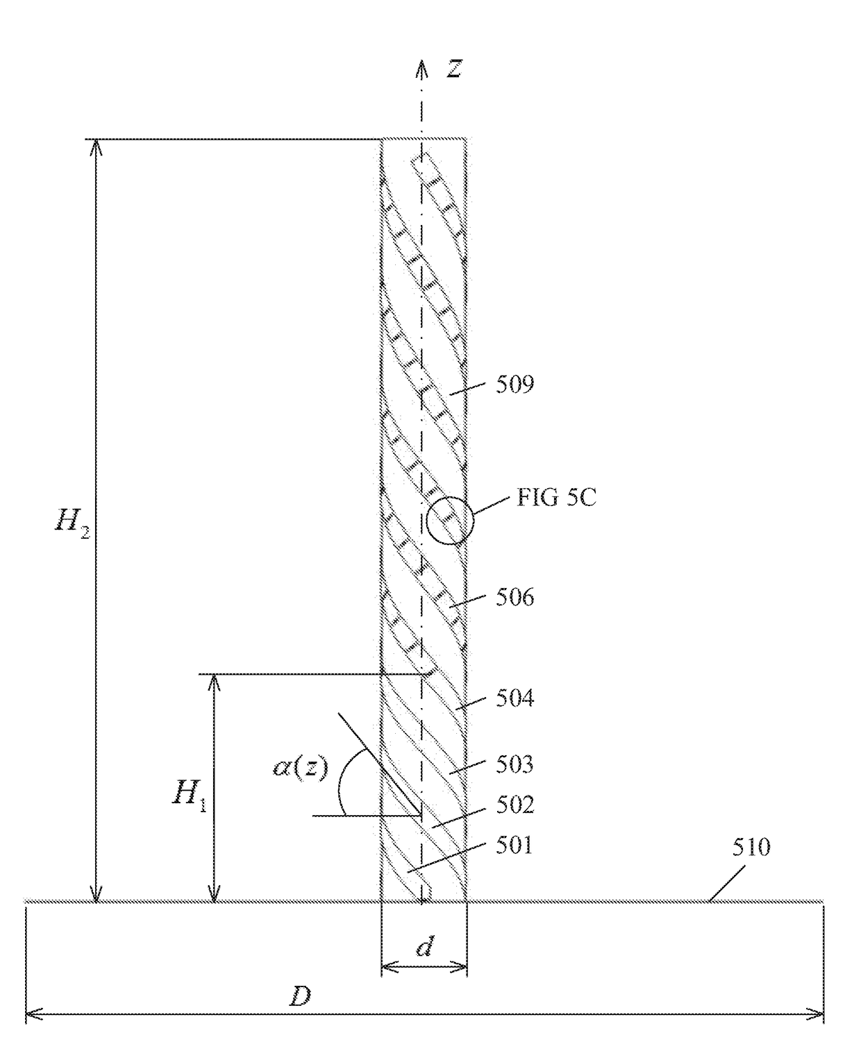
[0030]The proposed invention according to FIGS. 5A-5C is a quadrifilar cylindrical spiral antenna with capacitors soldered into breaks in metal turns.

[0031]The main features of the proposed antenna design are:[0032]1. A quadruple spiral (FIGS. 5A, 5B) with capacitors soldered in-between breaks of spiral turns that is located onto a ground plane.[0033]2. The diameter of the ground plane is selected such that a needed level of suppressing signals reflected from the ground in the nadir direction would be provided. In one of the embodiments, the diameter of the ground plane is 300 mm.[0034]3. The diameter of the spiral is D=30 + / −5 mm.[0035]4. Total height of the spiral H2 is H2=300 + / −50 mm.[0036]5. There is a free area with a height Hi where there are no capacitors H1=90 + / −30 mm.[0037]6. A variable winding angle is equal to

α(...


PUM


Abstract

A quadrifilar helix antenna includes a cylindrical support extending along an antenna axis; a plurality of spiral conductors wrapped helically on the cylindrical support and along the antenna axis from a feed end to a remote end; a circular ground plane perpendicular to the antenna axis; and each of the spiral conductors including a plurality of gaps, with the gaps having capacitors between conducting portions of the spiral conductors. The capacitors are positioned higher than 60 mm above the ground plane, and capacitance value varies inversely with height. The antenna exhibits a DU(10°=−20 dB or better at an operating frequency f0=1575 MHz. The diameter of the cylindrical support is 30 + / −5 mm. A total height of the cylindrical support is 300 + / −50 mm. A winding angle of the helix is variable.

Description

CROSS REFERENCE TO RELATED APPLICATIONS[0001]This application is a continuation of U.S. Patent Application Ser. No. 14 / 435646, filed on Apr. 14, 2015, which is a US National Phase of PCT / RU2014 / 000753, filed on Oct. 7, 2014, which are both incorporated by reference herein in their entirety.BACKGROUND OF THE INVENTIONField of the Invention[0002]The present invention is related to antennas, and, more particularly, to helical antennas for use in GPS receivers.Description of the Related Art[0003]Multipath error is currently one of the most important contributions to the GNSS positioning error budget when a signal reflected from the underlying ground surface is received at the output of the receiving antenna along with the line-of-sight signal. Multipath error is proportional to the ratioDU(θ)=F(-θ)F(θ)[0004]This ratio is typically called Down / Up ratio. Here, θ is the elevation angle over the local horizon, and F(+1−θ) is the directional diagram (DD) for the antenna at angle θ over and u...

Claims


Application Information

Patent Timeline
Patent Type & Authority Applications(United States)
IPC IPC(8): H01Q11/08H01Q1/48
CPCH01Q1/48H01Q11/08
Inventor TATARNIKOV, DMITRY VITALIEVICHCHERNETSKY, IVAN MIROSLAVOVICH
Owner TOPCON POSITIONING SYST INC
Features
  • Generate Ideas
  • Intellectual Property
  • Life Sciences
  • Materials
  • Tech Scout
  • Unparalleled Data Quality
  • Higher Quality Content
  • 60% Fewer Hallucinations
Learn More