Surgical instrument with articulated end-effector

a surgical instrument and end-effector technology, applied in the field of remote actuation mechanical systems, can solve the problems of inability to use laparoscopic procedures, long recovery periods in inpatient settings, and substantial blood loss, and achieve the effects of reducing the wear of the rope, and reducing the risk of infection

Active Publication Date: 2017-12-28
DISTALMOTION
View PDF4 Cites 21 Cited by
  • Summary
  • Abstract
  • Description
  • Claims
  • Application Information

AI Technical Summary

Benefits of technology

[0010]Theses aims and other advantages are achieved by a new articulated end-effector mechanism, designed to be used at the distal extremity of a surgical instrument shaft, in the form of, for example, a dissector, scissor or grasper. The shaft defines the longitudinal axis of the instrument and is able to move according to the mobility constraints imposed by a body incision, which includes a rotational movement about its own axis. This rotation also causes the rotation of the end-effector, mounted on the distal extremity of the shaft. Thus, the instrument shaft has the combined function of positioning the end-effector within the interior of the patient's body and allowing the passage of the different mechanical elements that are able to actuate the different distal end-effector articulations, by transmitting motion from an instrument hub, placed on the proximal extremity of the instrument shaft, to the distal end-effector articulations. These distal articulations of the end-effector are able to (1) operate the surgical instrument in order to accomplish its function (for example, grasping or cutting) and (2) provide orientation motions between the end effector and the instrument shaft.
[0011]The movement of each distal articulation of the end-effector is originated by the movement of a rotating element, located on the proximal hub, which is connected to a distal amplification element, placed on the instrument's end-effector, by flexible transmission elements passing through the instrument shaft. This distal amplification element is then able to transmit, and amplify, the movement to the respective end-effector link by a contact force. The amplification element is directly connected to the flexible transmission elements at a grooved geometry, having a pulley-like shape with a relatively large diameter, so that the wear of the ropes can be minimized.
[0012]In addition, this invention can provide short distances between the articulations of the end-effector and guaranteed simplified maintenance procedures if some moving links of the end-effector have to be removed.

Problems solved by technology

However, due to the long incision, this approach is extremely invasive for the patient, resulting in substantial blood loss during the surgery and long and painful recovery periods in an in-patient setting.
Therefore, due to the drawbacks of its instrumentation, laparoscopic procedures are mainly limited to use in simple surgeries, while only a small minority of surgeons is able to use them in complex procedures.
However, if the motion is transmitted from the proximal hub to each one of the distal articulations by rotating elements with non-independent range of rotation (like in the system disclosed in EP14159025—FIGS. 9 and 10), and not by an independent rotating spools, the actuating rotation of each one of the rotating elements is limited by the actuating rotation of the other rotating elements.
This limitation is particularly problematic when a broad range of motion is supposed to be achieved at the distal articulations and there are dimensional constraints on the diameter of distal pulleys given the diameter and construction of the actuation ropes.

Method used


Image

  • Surgical instrument with articulated end-effector
  • Surgical instrument with articulated end-effector
  • Surgical instrument with articulated end-effector

Examples


Embodiment Construction

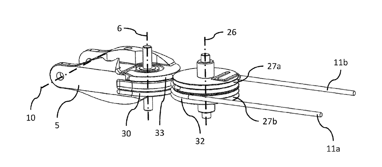
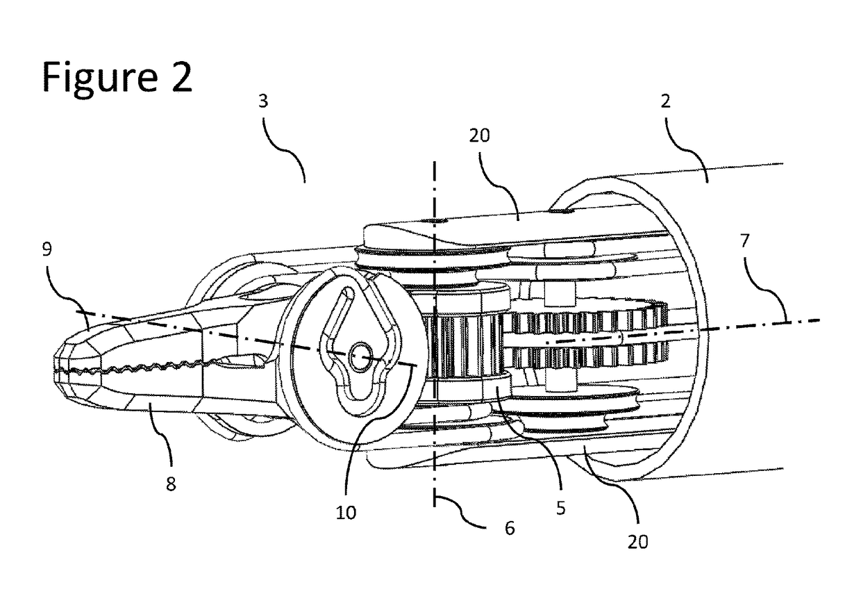
[0033]A surgical instrument 1 for minimally invasive surgical procedures, with an articulated end-effector constructed in accordance with an embodiment of the present invention, is described herein, and is seen generally in FIG. 1. This instrument 1 includes a main shaft 2, a distal end-effector 3 and a proximal hub 4. Referring to FIG. 2, the end-effector 3 is connected to the distal extremity of the main shaft 20 by a proximal joint, which allows the rotation of the proximal end-effector link 5 by the proximal axis 6 in such a manner that the orientation of the proximal end-effector link 5 with respect to the main shaft axis 7 can be changed.

[0034]Referring to FIG. 2, the distal end-effector links 8, 9 are rotatably connected to the proximal end-effector link 5 by two distal joints, having coincident axes of rotation, which are represented by the distal axis 10. This distal axis 10 is substantially perpendicular and non-intersecting with the proximal axis 6 and substantially inter...


PUM


Abstract

Disclosed is a surgical instrument with an articulated end-effector, such as a dissector, scissor or grasper, to enhance a surgeon's performance during various surgical procedures. The longitudinal axis of the instrument is defined by a shaft, which may be inserted into a surgical incision or trocar in a body of a patient. The articulated end-effector is mounted on the distal extremity of the instrument shaft and comprises a plurality of links interconnected by a plurality of joints, whose movements are remotely actuated by the surgeon's hands. This remote actuation is accomplished through mechanical transmission, mainly along flexible elements, which are able to deliver motion from a set of actuation elements, placed at a proximal extremity of the shaft, to the instrument's articulated end-effector. The articulated end-effector further comprises one or more movement-amplification elements that amplify the movement transmitted by the flexible elements so that the movement of the proximal actuation elements can be minimized while the fatigue resistance of the instrument is maintained or increased. In addition, this invention can provide short distances between the articulations of the end-effector and guaranteed simplified maintenance procedures if some moving links of the end-effector have to be removed.

Description

FIELD OF THE INVENTION[0001]The present invention relates to the field of remotely actuated mechanical systems, more particularly to endoscopic mechanisms, and most particularly to remotely actuated endoscopic surgical instruments. More specifically, this invention relates to endoscopic articulated mechanisms such as graspers, dissectors, and scissors, wherein the orientation of end-effectors in relation to the instrument shaft is able to be controlled. Most specifically, the invention relates to such mechanisms wherein the actuation and orientation of the instrument's distal end-effector is remotely performed, and transmitted from the proximal to the distal extremity of the instrument shaft, by mechanical transmission elements. This mechanism is intended to be used primarily in surgical procedures, where the instruments with articulated end-effectors are passing through incisions or trocars into a patient's body. It is also adapted for any suitable remote actuated application requi...

Claims


Application Information

Patent Timeline
Patent Type & Authority Applications(United States)
IPC IPC(8): A61B34/00A61B17/28A61B34/37
CPCA61B34/71A61B34/37A61B17/28A61B34/77
Inventor BEIRA, RICARDO DANIEL RITA
Owner DISTALMOTION
Why Eureka
Try Eureka