
Bipedal Isotropic Lattice Locomoting Explorer: Robotic Platform for Locomotion and Manipulation of Discrete Lattice Structures and Lightweight Space Structures

a robotic platform and isotropic technology, applied in the field of robotics, can solve the problems of limited scale difficult to achieve the effect of space application, and difficult to achieve the effect of achieving the effect of reducing the complexity of the object being buil

Active Publication Date: 2017-12-28
MASSACHUSETTS INST OF TECH +1
View PDF0 Cites 11 Cited by
  • Summary
  • Abstract
  • Description
  • Claims
  • Application Information

AI Technical Summary

Benefits of technology

The invention is a foot designed to fit snugly around the shape of a voxel structure using a latch mechanism driven by small servos. It is designed to prevent the foot from lifting off the structure and to ensure a tight grip to prevent any loosening of the connection. Overall, the technical effect of the invention is a more secure and stable connection between the foot and the voxel structure.

Problems solved by technology

However, this approach runs into issues for very large or complex structures.
Disadvantages or limitations of the prior art include: 1) Lattice building robots: the build volume of these gantry based robot platforms limits the scale of the object being built.
This enables it to perform much more complex maneuvers while also enabling interaction and manipulation with the structure that other robots, attaching with means such as suction cups, would be unable to achieve; 3) Relative structure robots: these are not suitable for space applications due to the density of the structure.
The construction of large space structures has been a challenge due to the limitations of human-based extravehicular activity (EVA) and robot-based extravehicular robotics (EVR).
Both approaches face problems regarding risk, throughput, and reliability [M. D. Rhodes, R. W. Will, and C. Quach, “Baseline Tests of an Autonomous Telerobotic System for Assembly of Space Truss Structures,” Langley, 1994] [M. Lake, W. Heard, J. Watson, and T. J. Collins, “Evaluation of Hardware and Procedures for Astronaut Assembly and Repair of Large Precision Reflectors,” Langley, 2000].
Relative structure robots in general, and AMAS in particular, may not be suitable for space applications due to the density of the structure.

Method used


Image

  • Bipedal Isotropic Lattice Locomoting Explorer: Robotic Platform for Locomotion and Manipulation of Discrete Lattice Structures and Lightweight Space Structures
  • Bipedal Isotropic Lattice Locomoting Explorer: Robotic Platform for Locomotion and Manipulation of Discrete Lattice Structures and Lightweight Space Structures
  • Bipedal Isotropic Lattice Locomoting Explorer: Robotic Platform for Locomotion and Manipulation of Discrete Lattice Structures and Lightweight Space Structures

Examples


Embodiment Construction

Methodology

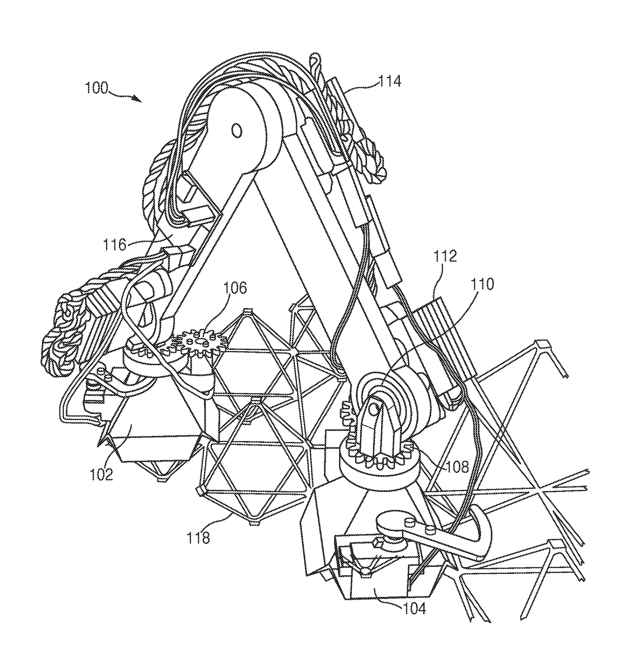
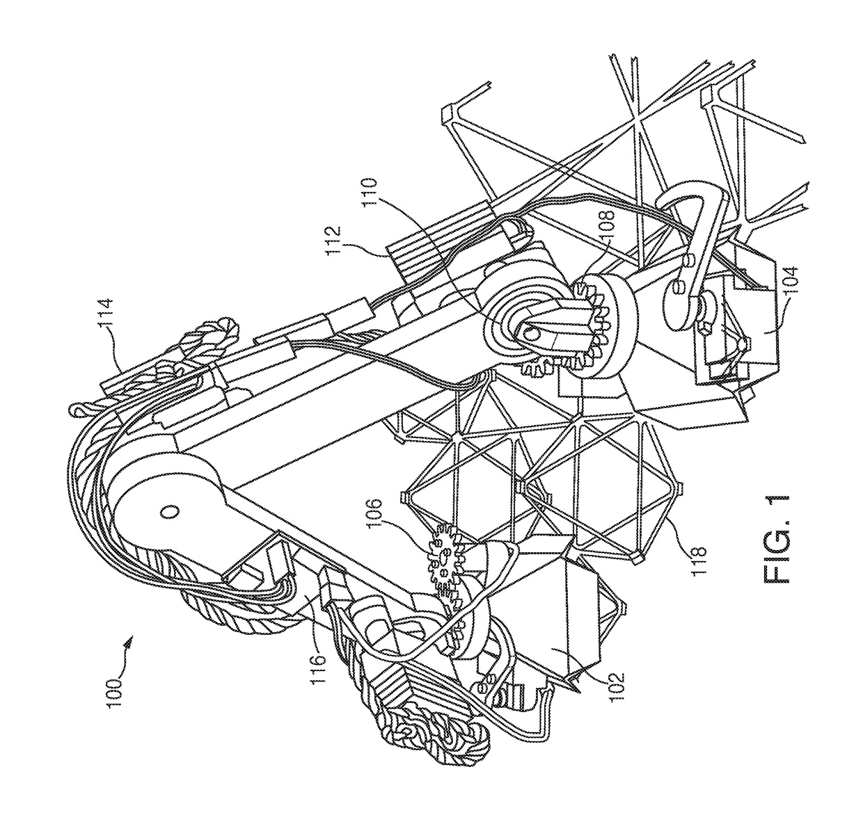
[0056]FIG. 1 depicts an example Bipedal Isotropic Lattice Locomoting Explorer (BILL-E) 100 on a lattice structure 118 with its main components. Bill-E's main components are a foot 102, a foot servo motor with latch 104, a lower leg motor with gear 106, a lower leg with integral gear 108, a lower leg to upper leg bearing interface 110, an upper leg servo motor with rigid connection to lower leg 112, a hip motor and bearing interface 114, and a microcontroller 116.

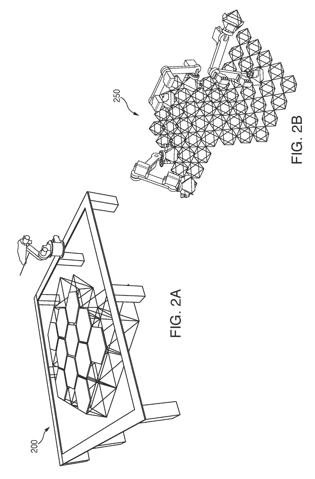
[0057]FIGS. 2A-2B show a comparison of robotic assembly platforms for space structures. FIG. 2A depicts a gantry-based robotic arm assembly system 200, based on work from [W. R. Doggett, “Robotic Assembly of Truss Structures for Space Systems and Future Research Plans,” in IEEE Aerospace Conference Proceedings, 2002]. As shown in FIG. 2A, robots can be mounted to linear gantries to increase the available build area for a given robot. FIG. 2B depicts a relative robotic system 250 enabling the construction of arbitr...


PUM


Abstract

A robotic platform for traversing and manipulating a modular 3D lattice structure is described. The robot is designed specifically for its tasks within a structured environment, and is simplified in terms of its numbers of degrees of freedom (DOF). This allows for simpler controls and a reduction of mass and cost. Designing the robot relative to the environment in which it operates results in a specific type of robot called a “relative robot”. Depending on the task and environment, there can be a number of relative robots. This invention describes a bipedal robot which can locomote across a periodic lattice structure made of building block parts. The robot is able to handle, manipulate, and transport these blocks when there is more than one robot. Based on a general inchworm design, the robot has added functionality while retaining minimal complexity, and can perform numerous maneuvers for increased speed, reach, and placement.

Description

[0001]This application is a continuation of International Application No. PCT / US17 / 39246, filed Jun. 26, 2017, and claims the benefit of U.S. Provisional Application No. 62 / 355,008, filed Jun. 27, 2016, and U.S. Provisional Application No. 62 / 384,302, filed Sep. 7, 2016, the entire disclosures of which are herein incorporated by reference.[0002]This invention was made with government support under Grant / Contract No. NNX14AG47A awarded by NASA, and Grant / Contract No. NNX14AM40H S01 awarded by NASA. The government has certain rights in the invention.TECHNICAL FIELD OF THE INVENTION[0003]The present invention relates to robotics, particularly a robot designed to locomote on the outside of a specific lattice structure.BACKGROUND OF THE INVENTION[0004]The general description of the problem and objective is as follows. Large structures can be assembled from smaller discrete parts. This has several benefits including the mass production of parts, the assembly and disassembly of parts for r...

Claims


Application Information

Patent Timeline
Patent Type & Authority Applications(United States)
IPC IPC(8): B25J9/00B25J9/16B25J13/00B25J9/04B64G4/00B25J17/02B25J18/00
CPCB25J9/009B25J9/0096B25J9/0009B25J9/04B25J9/1682G05B2219/45083B64G4/00B25J18/00B25J17/02B64G2004/005B25J13/006B25J15/0033B25J9/0084B25J9/06B25J15/0206B62D57/032B64G1/244B64G1/38B64G1/44B62D57/02
Inventor JENETT, BENJAMINCHEUNG, KENNETHGERSHENFELD, NEIL
Owner MASSACHUSETTS INST OF TECH
Learn More