Control system for hybrid vehicle

a control system and hybrid technology, applied in battery/cell propulsion, engine-driven generator propulsion, transportation and packaging, etc., can solve the problems of increasing electrical loss resulting from such power conversion, reducing energy efficiency of hybrid vehicles, and increasing electrical loss, so as to reduce losses

Active Publication Date: 2017-12-28
TOYOTA JIDOSHA KK
View PDF4 Cites 16 Cited by
  • Summary
  • Abstract
  • Description
  • Claims
  • Application Information

AI Technical Summary

Benefits of technology

[0005]Aspects of the present invention have been conceived noting the foregoing technical problems, and it is therefore an object of the present application is to provide a control system for a hybrid vehicle that can reduce a loss resulting from shifting an operating mode from electric vehicle mode in which an engine is stopped to hybrid mode in which the engine is activated.
[0009]In a non-limiting embodiment, the threshold value of the driving force may be increased with an increase in the vehicle speed.
[0014]Thus, according to the embodiment of the present disclosure, the engine is started in the high mode if the vehicle speed is higher than the threshold value during propulsion in the electric vehicle mode, and the engine is started in the low mode if the vehicle speed is lower than the threshold value during propulsion in the electric vehicle mode. In the low mode, the torque ratio of the output element to the input element is larger than that in the high mode. That is, when the vehicle is propelled by the motor(s) at a high speed, output torque of the first motor may be reduced to start the engine in the high mode. According to the embodiment of the present disclosure, therefore, occurrence of power circulation may be avoided to reduce an electrical loss resulting from starting the engine. By contrast, during propulsion in the low mode at a low speed, a percentage of the torque delivered directly from the engine to the output unit without passing through the reaction element such as the first motor is increased, and consequently the torque delivered to the output unit through the second motor while being temporarily converted into an electric power by the first motor is reduced. For this reason, a power loss may be reduced in the hybrid vehicle.
[0016]Further, according to the embodiment of the present disclosure, the engine is started in the high mode if the required driving force is smaller than the threshold value, even if the vehicle speed is lower than the threshold value. According to the embodiment of the present disclosure, therefore, a difference between rotational speeds of the first motor before and after starting the engine can be reduced. For this reason, a power loss resulting from starting the engine can be reduced.
[0017]In addition, if the detected temperature is low, startup of the engine in the high mode is inhibited and the engine is started in the low mode. According to the embodiment of the present disclosure, therefore, the engine can be started by the amplified torque of the first motor so that the engine can be started easily even if the temperature is low.

Problems solved by technology

However, if the engine is started in the high stage at a low speed, an electrical loss may be increased.
Thus, the power delivered to the driveshaft while being converted temporarily into electric power is increased and hence the electrical loss resulting from such power conversion is increased.
For this reason, energy efficiency in the hybrid vehicle may decrease if the engine is started in the high stage.
Given that the threshold value of the vehicle speed is set outside of the range between the first vehicle speed and the second vehicle speed, and that the operating mode is shifted between the high mode and the low mode based on such threshold value, an electrical loss resulting from starting the engine may not be reduced sufficiently.
In addition, if the detected temperature is low, startup of the engine in the high mode is inhibited and the engine is started in the low mode.

Method used


Image

  • Control system for hybrid vehicle
  • Control system for hybrid vehicle
  • Control system for hybrid vehicle

Examples


Embodiment Construction

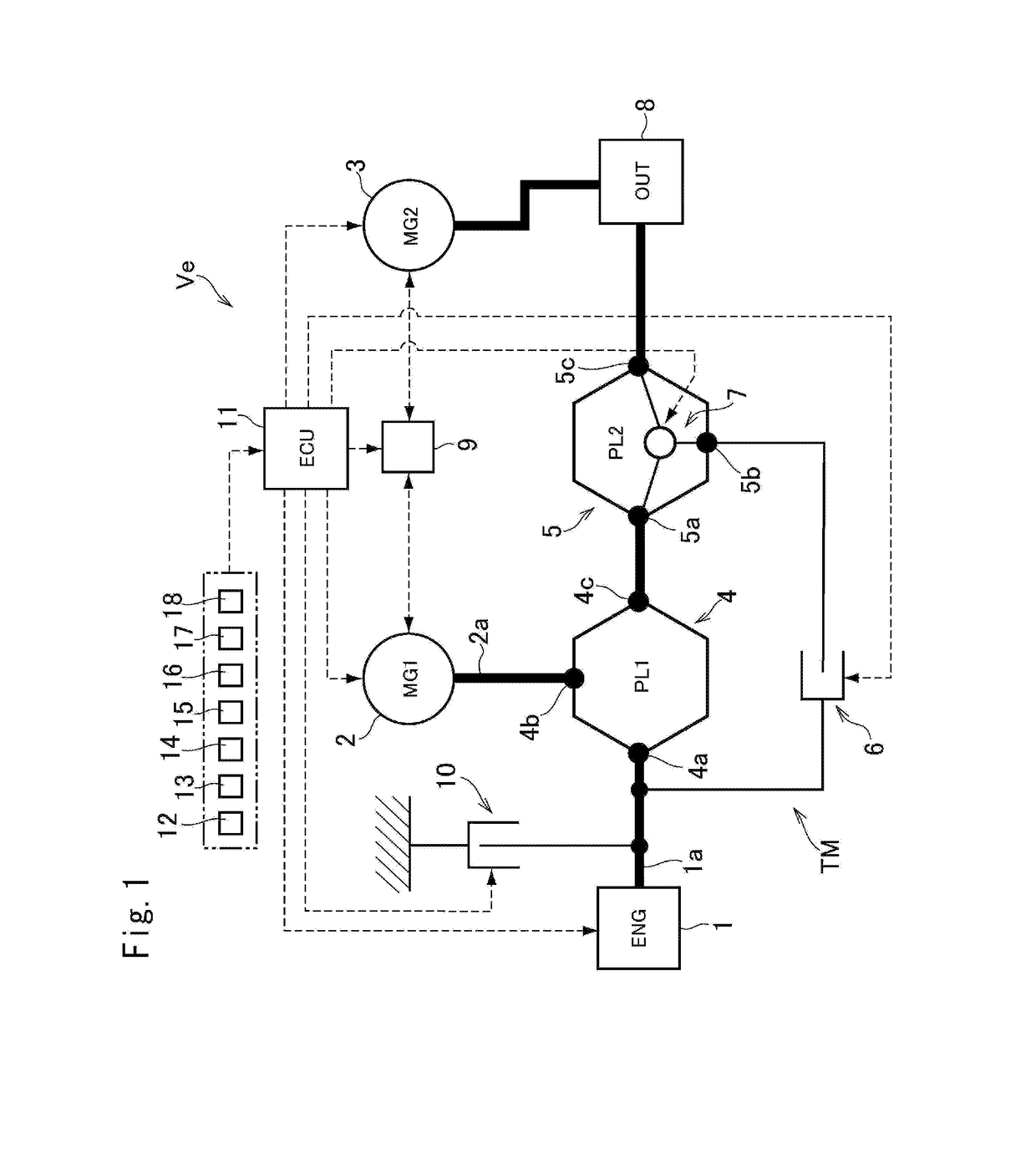
[0047]Preferred embodiments of the present application will now be explained with reference to the accompanying drawings. Referring now to FIG. 1, there is shown one example of a drive system of a hybrid vehicle to which the control system according to the present disclosure is applied. A prime mover of the vehicle Ve shown in FIG. 1 includes an engine (referred to as “ENG” in FIG. 1) 1, a first motor (referred to as “MG1” in FIG. 1) 2, and a second motor (referred to as “MG2” in FIG. 1) 3. A power train of the vehicle Ve includes a first planetary gear unit (referred to as “PL1” in FIG. 1) 4, a second planetary gear unit (referred to as “PL2” in FIG. 1) 5, a first engagement device 6, a second engagement device 7 and an output unit 8 (referred to as “OUT” in FIG. 1).

[0048]Power of the engine 1 is distributed to the first motor 2 side and to the output unit 8 side through the first planetary gear unit 4 serving as a power distribution device. The first motor 2 and the second motor 3...


PUM


Abstract

A control system for a hybrid vehicle that can reduce a power loss resulting from shifting an operating mode from motor mode to hybrid mode is provided. A transmission that is adapted to distribute torque applied to an input element to a reaction element and an output element, and to change a ratio between a first torque delivered to the reaction element and a second torque delivered to the output element. A controller is configured to start an engine in a high mode in which a torque ratio of the output element to the input element is small if the vehicle speed is higher than a threshold value, and to start the engine in a low mode in which the torque ratio is greater if the vehicle speed is lower than the threshold value.

Description

CROSS REFERENCE TO RELATED APPLICATIONS[0001]The present invention claims the benefit of priority to Japanese Patent Application No. 2016-126924 filed on Jun. 27, 2016 with the Japanese Patent Office.BACKGROUNDField of the Invention[0002]Embodiments of the present invention relate to a control system for a hybrid vehicle in which a prime mover includes an engine and a motor.Discussion of the Related Art[0003]JP-A-2014-51146 describes one example of a hybrid vehicle having an engine, a first motor and a second motor. In the hybrid vehicle taught by JP-A-2014-51146, power of the engine is distributed to the first motor and a driveshaft through a first single-pinion planetary gear unit serving as a power distribution device. Electricity generated by the first motor is supplied to the second motor so that power of the second motor is added to the driveshaft. A second single-pinion planetary gear unit is disposed between the first single-pinion planetary gear unit and the driveshaft to s...

Claims


Application Information

Patent Timeline
Patent Type & Authority Applications(United States)
IPC IPC(8): B60L11/12B60W20/10B60L15/20B60K6/46B60L50/15B60W10/06B60W10/08
CPCB60L11/126B60L15/20B60K6/46B60W20/10B60L2240/441B60W10/08B60L2240/12B60L2240/421B60W10/06B60K6/365B60K6/387B60K6/445B60K2006/381B60L2240/423B60L2240/443B60L2260/26B60W10/02B60W20/20B60W2510/0676B60W2510/1005B60W2510/1015B60W2510/104B60W2520/10B60L50/16B60L50/61B60W2555/20Y02T10/40Y02T10/62Y02T10/64Y02T10/70Y02T10/7072Y02T10/72Y02T10/92B60W20/30B60L50/62
Inventor ENDO, TAKAHITONAGAI, HIDEKAZUHATA, KENSEIMURAKAMI, AKIRA
Owner TOYOTA JIDOSHA KK
Why Eureka
Try Eureka