Angle sensor and angle sensor system

a sensor and angle technology, applied in the direction of electrical/magnetically converting sensor output, measuring devices, instruments, etc., can solve the problems of affecting the accuracy of the detection signal, the distortion of the waveform of each detection signal, and the error of the detected angle value, so as to achieve the effect of reducing the angular error

Active Publication Date: 2017-12-28
TDK CORPARATION
View PDF3 Cites 8 Cited by
  • Summary
  • Abstract
  • Description
  • Claims
  • Application Information

AI Technical Summary

Benefits of technology

[0012]It is an object of the present invention to provide an angle sensor and an angle sensor system capable of easily reducing an angular error resulting from an error component corresponding to a fifth or higher-order harmonic contained in each of a plurality of detection signals.

Problems solved by technology

However, there are cases where the waveform of each detection signal is distorted from a sinusoidal curve.
A distortion of the waveform of each detection signal may result in some error in the detected angle value.
A distortion of the waveform of each detection signal may also be caused by the combination of the first cause and the second cause.
However, such a method requires complicated signal processing.
This problem becomes more noticeable as the order of the one or more harmonics corresponding to the one or more error components becomes higher.
The technique described in US 2012 / 0053865 A1 is not capable of reducing an angular error caused by an error component corresponding to a fifth or higher-order harmonic.
The technique described in JP H05-346329A requires designing of the magnetoresistance element with the positions of the plurality of linear magnetoresistance element pieces varied in accordance with intervals of the calibration of the magnetic scale, thus causing difficulty in the design of the magnetoresistance element.

Method used


Image

  • Angle sensor and angle sensor system
  • Angle sensor and angle sensor system
  • Angle sensor and angle sensor system

Examples


first embodiment

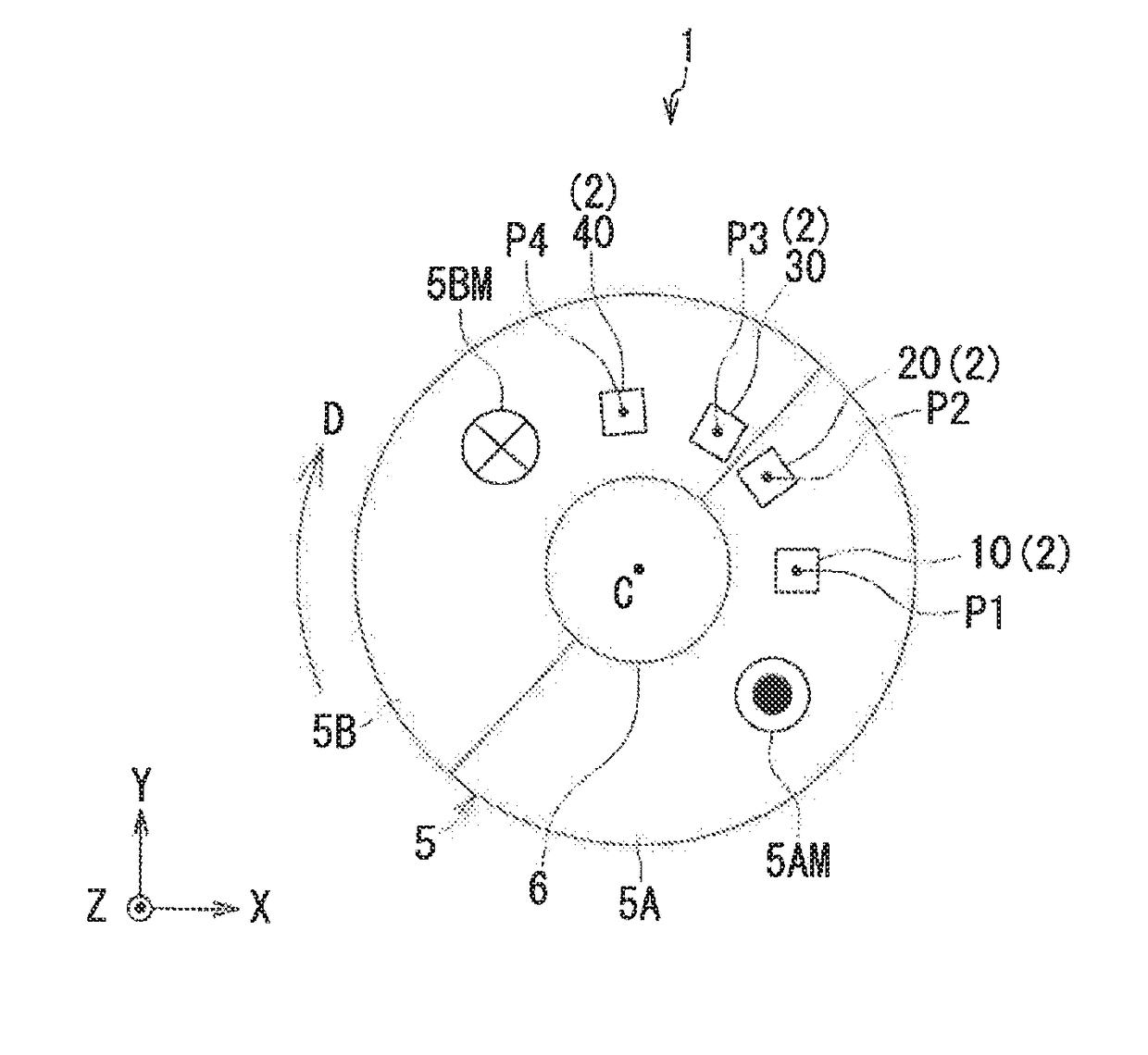
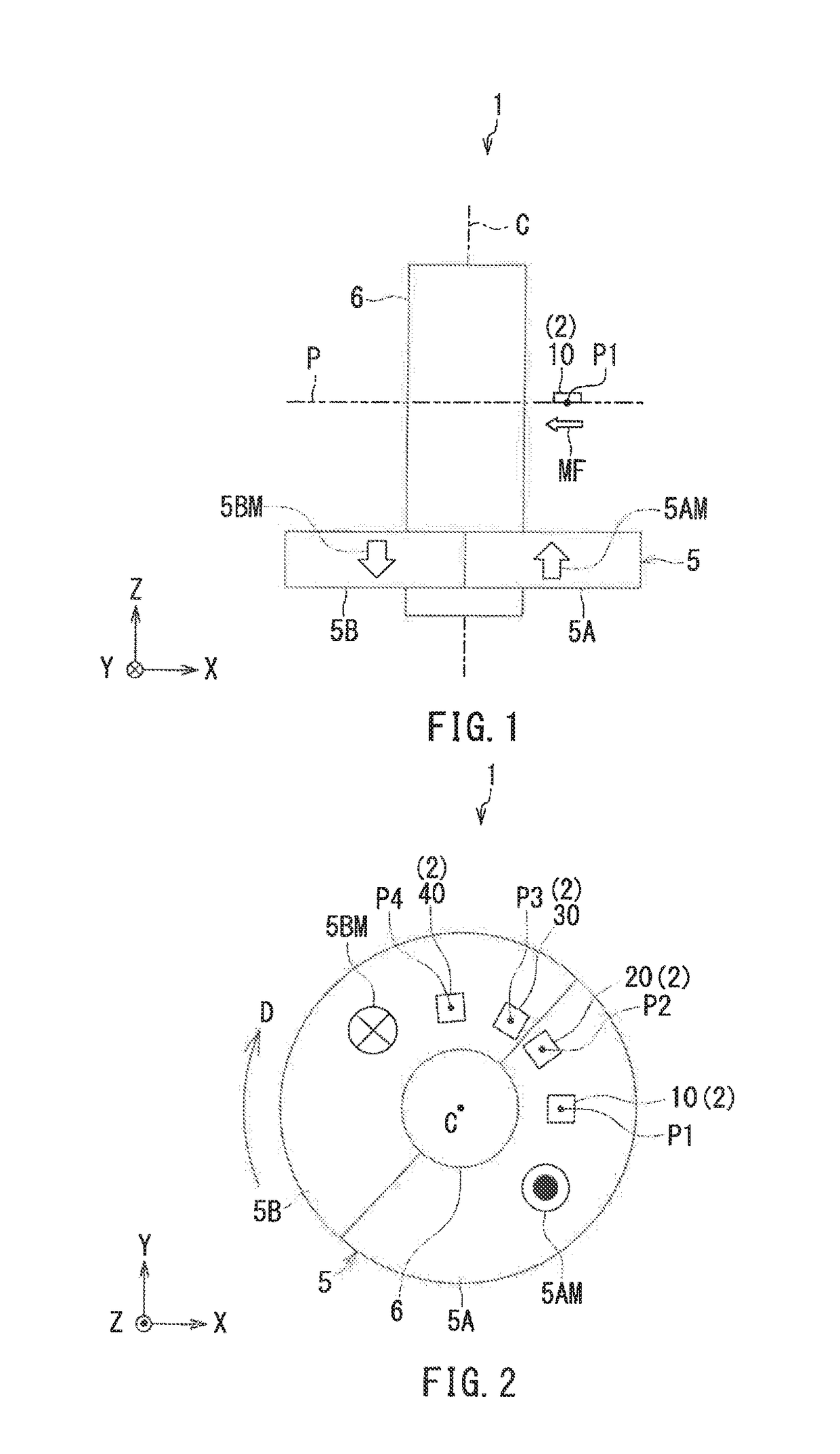
[0061]Preferred embodiments of the present invention will now be described in detail with reference to the drawings. First, reference is made to FIG. 1 and FIG. 2 to describe the general configuration of an angle sensor system according to a first embodiment of the invention. The angle sensor system 1 according to the first embodiment includes an angle sensor 2 according to the first embodiment. The angle sensor 2 according to the first embodiment is a magnetic angle sensor, in particular. As shown in FIGS. 1 and 2, the angle sensor system 1 further includes a magnetic field generation unit 5 for generating a rotating magnetic field MF whose direction rotates. The angle sensor 2 is configured to generate a detected angle value having a correspondence with an angle that the direction of the rotating magnetic field MF in a reference position forms with respect to a reference direction. Hereinafter, the angle that the direction of the rotating magnetic field MF in a reference position ...

second embodiment

[0173]A second embodiment of the invention will now be described. First, reference is made to FIG. 13 to describe the general configuration of an angle sensor system according to the second embodiment. The angle sensor system 1 according to the second embodiment differs from that according to the first embodiment in the following ways. The angle sensor system 1 according to the second embodiment includes a magnetic field generation unit 7 in place of the magnetic field generation unit 5 of the first embodiment. The magnetic field generation unit 7 of the present embodiment is a magnet of a cylindrical shape for generating a rotating magnetic field MF whose direction rotates. The magnetic field generation unit 7 rotates about a central axis C in a rotational direction D.

[0174]The magnetic field generation unit 7 includes a first portion 7A and a second portion 7B magnetized in mutually different directions. The first portion 7A and the second portion 7B are arranged symmetrically wit...

third embodiment

[0194]A third embodiment of the invention will now be described. First, reference is made to FIG. 15 to describe the general configuration of the angle sensor system according to the third embodiment. The angle sensor system 1 according to the third embodiment differs from that according to the first embodiment in the following ways. The angle sensor system 1 according to the third embodiment includes a magnetic field generation unit 8

[0195]In FIG. 15, the X direction is rightward, the Y direction is upward, and the Z direction is out of the plane of the drawing. The magnetic field generation unit 8 includes a plurality of sets of the first and second portions 8A and 8B arranged alternately in a linear configuration along the X direction. The first portion 8A and the second portion 8B are magnetized in mutually opposite directions. In FIG. 15, the hollow arrows indicate the magnetization directions of the portions 8A and 8B. In FIG. 15, each first portion 8A is magnetized in the Y d...


PUM


Abstract

An angle sensor includes a first to a fourth detection unit and an angle detection unit. Each of the first to the fourth detection unit generates two detection signals. The first to the fourth detection unit are arranged in a positional relationship that establishes predetermined phase relationships among the detection signals they generate. The angle detection unit performs operations using the detection signals to generate a first and a second signal in which an error component corresponding to a fifth or higher-order harmonic and an error component corresponding to a harmonic of the order other than the fifth order are lower than those in the detection signals. The angle detection unit then calculates a detected angle value on the basis of the first and the second signal.

Description

BACKGROUND OF THE INVENTION1. Field of the Invention[0001]The present invention relates to an angle sensor and an angle sensor system for generating a detected angle value having a correspondence with an angle that the direction of a rotating magnetic field forms with respect to a reference direction.2. Description of the Related Art[0002]In recent years, angle sensors have been widely used in various applications, such as detection of the rotational position of a steering wheel or a power steering motor in an automobile. The angle sensors generate a detected angle value having a correspondence with an angle to be detected. Examples of the angle sensors include a magnetic angle sensor. An angle sensor system using a magnetic angle sensor is typically provided with a magnetic field generation unit for generating a rotating magnetic field whose direction rotates in response to the rotation or linear movement of an object. The magnetic field generation unit is a magnet, for example. Th...

Claims


Application Information

Patent Timeline
Patent Type & Authority Applications(United States)
IPC IPC(8): G01D5/16
CPCG01D5/16G01D5/145G01D5/24485
Inventor UCHIDA, KEISUKEWATANABE, KAZUYAHIRABAYASHI, HIRAKU
Owner TDK CORPARATION
Why Eureka
Try Eureka