Electrical energy storage apparatus having improved coupling structure of internal terminal

a technology of electrical energy storage and internal terminals, which is applied in the direction of wound/folded electrode electrodes, cell components, sustainable manufacturing/processing, etc., can solve the problems of difficult to effectively cope with an increased internal pressure of the metal case, poor internal gas release performance, and inability to ensure easy maintenance and long service life. , to achieve the effect of improving electrolyte impregnation, enhancing internal gas release performance, and easy control

Active Publication Date: 2017-12-28
LS MATERIALS CO LTD
View PDF9 Cites 6 Cited by
  • Summary
  • Abstract
  • Description
  • Claims
  • Application Information

AI Technical Summary

Benefits of technology

[0021]According to the present disclosure, when the internal terminal and the electrode leads are coupled, the shape of the electrode leads is partially maintained to ensure smooth impregnation of the electrolyte, thereby greatly improving the electrolyte impregnation and enhancing the internal gas release performance.
[0022]In addition, the area of the electrode leads where the shape is maintained and the contact resistance thereof may be easily controlled by means of the structure of a connection rib of the internal terminal.

Problems solved by technology

The high capacitance storage device is sometimes used in place of a battery for applications which do not ensure easy maintenance and demand long service life.
However, in the existing high capacitance storage device, since the internal terminal of a plate shape is compressed on the entire leads, a channel is not properly secured and the internal gas release performance is poor.
Thus, even though the curling portion 41 is provided as above, it is difficult to effectively cope with an increased internal pressure of the metal case 40.
In addition, when the existing internal terminal 20 is coupled to the cell assembly 10, the lower surface of the internal terminal 20 is compressed onto the entire electrode leads 11, which disturbs impregnation of the electrolyte and thus does not ensure smooth impregnation.
This problem is more severe when a high-viscosity electrolyte is used.

Method used


Image

  • Electrical energy storage apparatus having improved coupling structure of internal terminal
  • Electrical energy storage apparatus having improved coupling structure of internal terminal
  • Electrical energy storage apparatus having improved coupling structure of internal terminal

Examples


Embodiment Construction

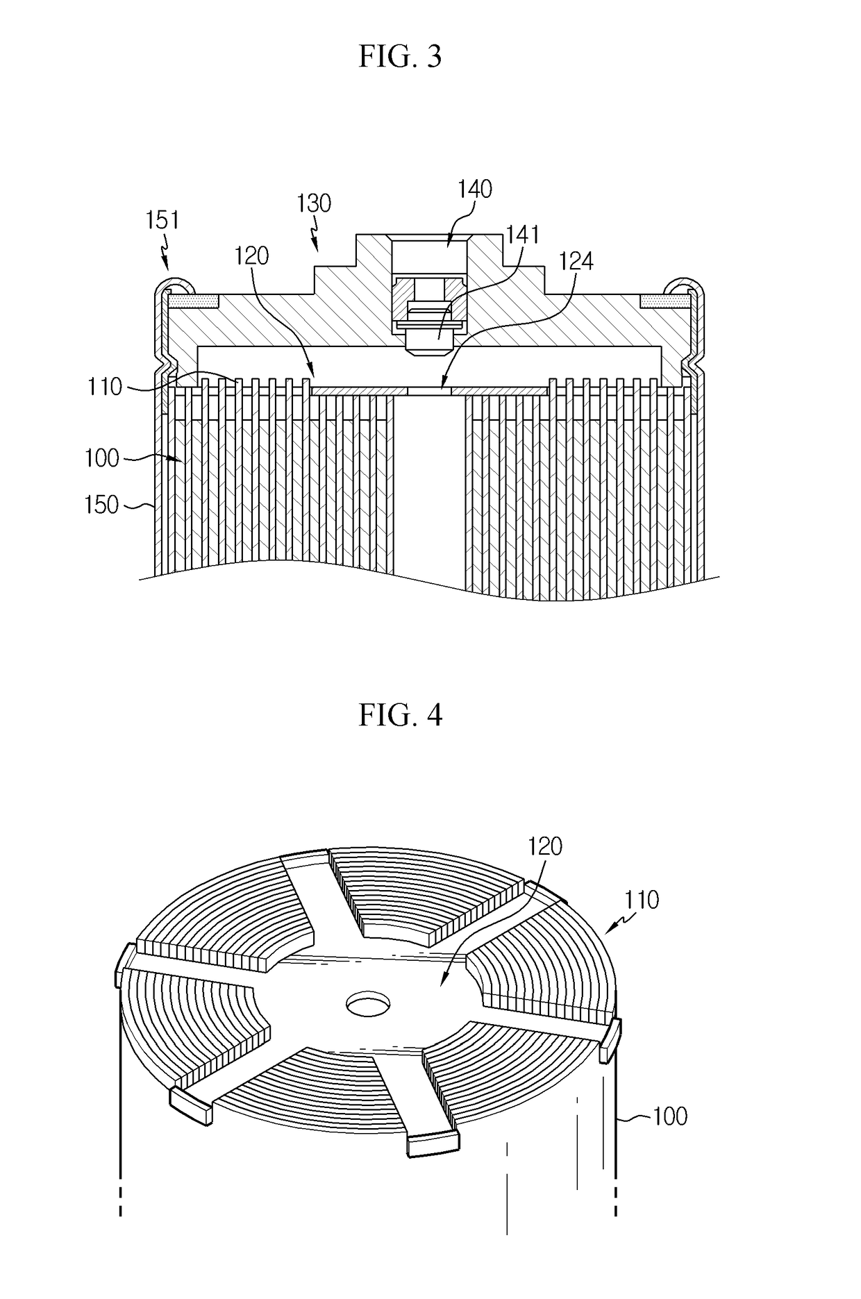
[0036]FIG. 3 is a cross-sectional view showing an electric energy storage device according to an embodiment of the present disclosure.

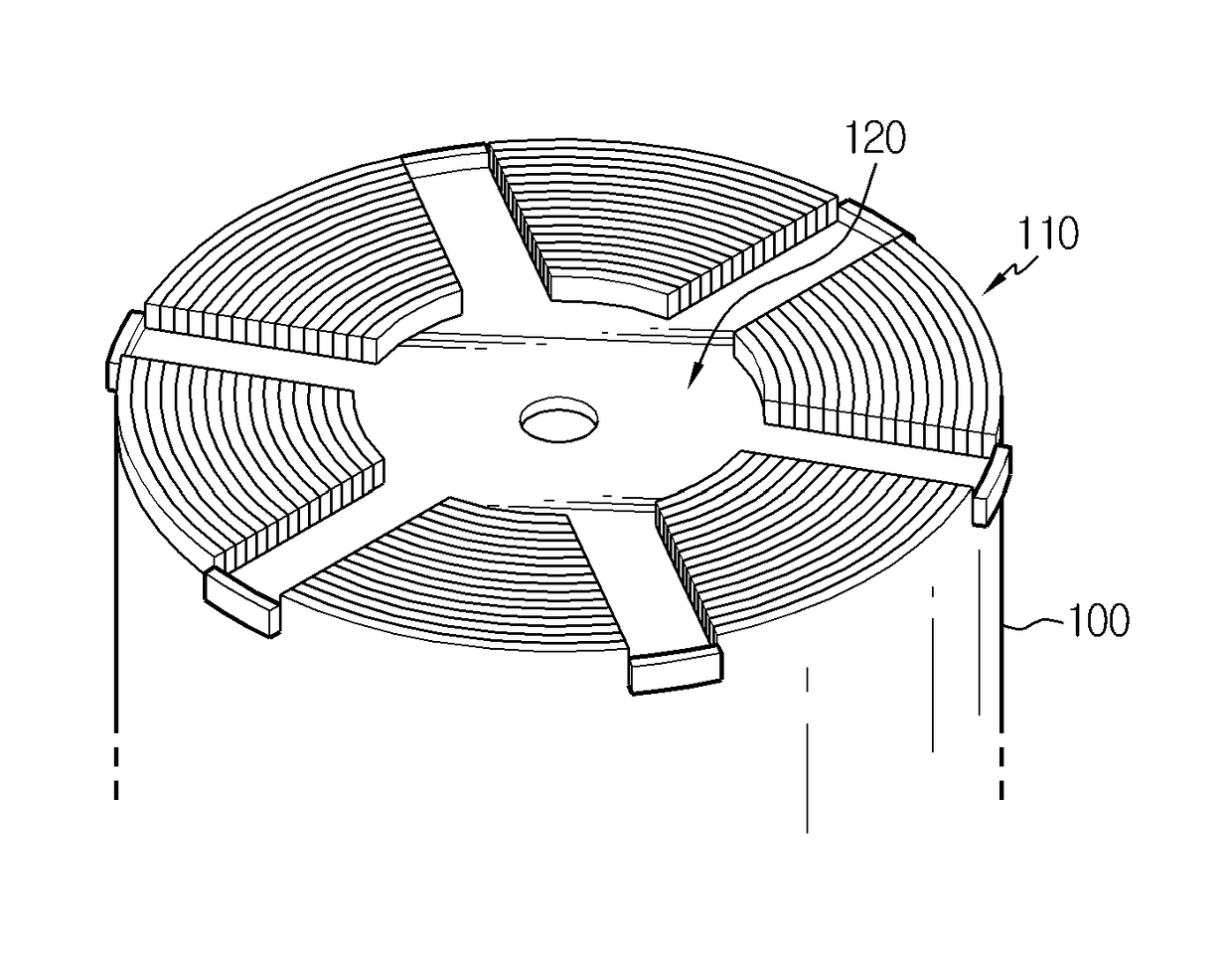
[0037]Referring to FIG. 3, the electric energy storage device according to an embodiment of the present disclosure includes a cell assembly 100, a cylindrical metal case 150 accommodating the cell assembly 100, an internal terminal 120 disposed inside an end of the metal case 150 and connected to the cell assembly 100 and having a radial body, and an external terminal 130 exposed to the outside in contact with the internal terminal 120.

[0038]The cell assembly 100 may adopt a general cell for an ultra-capacitor, in which a positive electrode plate and a negative electrode plate are wound together with a separator being interposed therebetween to form a jelly-roll shape. Electrode leads 110 respectively connected to the positive electrode plate and the negative electrode plate are located at both end surfaces of the cell assembly 100.

[0039]The metal cas...


PUM

PropertyMeasurementUnit
shapeaaaaaaaaaa
areaaaaaaaaaaa
sizeaaaaaaaaaa

Abstract

An electric energy storage device in which a cell assembly having electrode leads is installed in a metal case. The electric energy storage device includes an internal terminal formed with a support, connection ribs and thorough portions, and the electrode leads include a part of electrode leads compressed by the support and the connection ribs of the internal terminal and a part of electrode leads located at the thorough portions of the internal terminal to maintain a shape thereof.

Description

BACKGROUND OF THE INVENTION1. Field of the Invention[0001]The present application claims priority to Korean Patent Application No. 10-2015-0006839 filed on Jan. 14, 2015 in the Republic of Korea, the disclosures of which are incorporated herein by reference.[0002]The present disclosure relates to an electric energy storage device, and more particularly, to an electric energy storage device having a structure capable of improving electrolyte impregnation and internal gas discharging performance.2. Description of Related Art[0003]A high capacitance storage device, which is regarded as a next-generation electric energy storage device, includes a ultra-capacitor (UC), a super capacitor (SC), an electric double layer capacitor (EDLC) and the like, which are a kind of capacitor, and it is an energy storage device having an intermediate property between an electrolytic condenser and a secondary battery, which can be used in combination with, or in place of, a secondary battery due to its h...

Claims


Application Information

Patent Timeline
Patent Type & Authority Applications(United States)
IPC IPC(8): H01G11/12H01G11/22H01G11/72H01G11/76H01M50/538H01M50/627
CPCH01G11/12H01G11/76H01G11/72H01G11/22H01M50/538H01M50/627H01G11/82H01M4/70H01M10/0431Y02T10/70Y02E60/10Y02P70/50Y02E60/13H01M50/60
Inventor YOON, YU-ILLEE, HA-YOUNGBAE, SANG-HYUNSHIN, DONG-ILKO, HYUN-SEOKPARK, KYEONG-HOONKANG, HO-LIM
Owner LS MATERIALS CO LTD
Why Eureka
Try Eureka