Electrode assembly including electrode and separator partially bonded to each other

a technology of electrolyte and separator, which is applied in the field of electrolyte assembly, can solve the problems of deterioration of electrolyte impregnation, difficult to readily discharge a gas generated during a process, and deformation of the electrolyte assembly, so as to achieve the effect of reducing internal resistance and facilitating discharg

Active Publication Date: 2019-11-21
LG ENERGY SOLUTION LTD
View PDF6 Cites 1 Cited by
  • Summary
  • Abstract
  • Description
  • Claims
  • Application Information

AI Technical Summary

Benefits of technology

[0011]The present disclosure provides an electrode assembly in which an internal resistance can be decreased while adhesion between an electrode and a separator is maintained and a gas can be readily discharged while electrolyte impregnation is improved.

Problems solved by technology

Stress caused by expansion and contraction of electrodes during charging and discharging processes of a battery cell is accumulated in the electrode assembly, and when such stress accumulation exceeds a certain limit, the electrode assembly may be deformed.
Further, excessive adhesion may cause deterioration of electrolyte impregnation and make it difficult to readily discharge a gas generated during a process.

Method used


Image

  • Electrode assembly including electrode and separator partially bonded to each other
  • Electrode assembly including electrode and separator partially bonded to each other
  • Electrode assembly including electrode and separator partially bonded to each other

Examples


embodiments

[0083]Hereinafter, the present disclosure will be described in detail. Prior to the detailed description, it should be appreciated that terms and words used in the present specification and claims are not to be construed as a general or dictionary meaning, but are to be construed to meaning and concepts meeting the technical ideas of the present disclosure based on a principle that the inventors can appropriately define the concepts of terms in order to describe their own inventions in the best manner. Accordingly, description of this specification and illustrations of the drawings are merely given as an exemplary embodiment of the present disclosure and are not intended to represent all technical ideas of the present disclosure. Therefore, it should be understood that various equivalents and modifications can exist which can replace the embodiments described at the time of application.

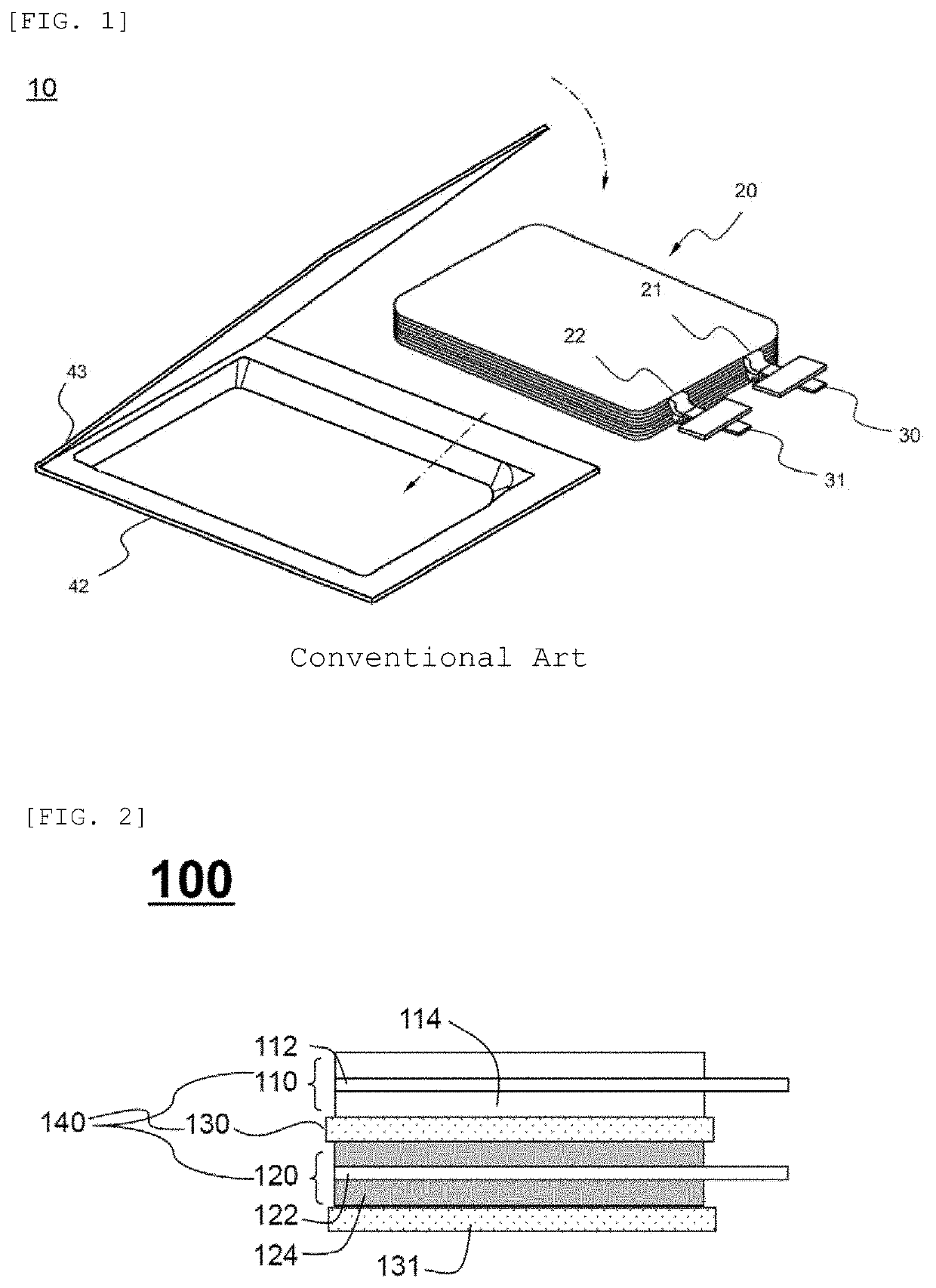
[0084]FIG. 2 is a side view illustrating an electrode assembly for secondary battery according to ...

example 1

[0104]A cathode containing a cathode active material and an anode containing an anode active material were prepared, and a separator including a porous coating layer containing SiO2 particles and PVdF and having a thickness of 5 μm formed on both surfaces of a polyolefin substrate having a thickness of 20 μm was prepared. A corona discharging process was performed to the separator along a pattern such that a non-processed area was formed on a central portion 26 mm away from each of both ends. The separator was interposed between the cathode and the anode to manufacture an electrode assembly having a size of 84 mm×84 mm.

example 2

[0109]A cathode mixture slurry was prepared by adding a cathode active material (e.g., LiCoO2) with a conductor and a binder (PVdF) at a weight ratio of 95:2.5:2.5 (active material: conductor: binder) to a solvent NMP (N-methyl-2-pyrrolidone), and an anode mixture slurry was prepared by adding synthetic graphite of 95 wt % as an anode active material, a conductor (Super-P) of 1.5 wt %, and a binder (PVdF) of 3.5 wt % to a solvent NMP and then coated, dried, and compressed on aluminum foil and copper foil, respectively, to prepare a cathode and an anode.

[0110]A separator was prepared using porous polyethylene, and surfaces of both sides of the separator facing the cathode and the anode were modified by a corona discharge. The porous polyethylene separator was interposed between the cathode and the anode and then heated and compressed such that a bonding interface between the electrode and the separator bonded to each other was partially bonded to 90% of the size of an entire interfac...


PUM

PropertyMeasurementUnit
temperatureaaaaaaaaaa
thicknessaaaaaaaaaa

Abstract

An electrode assembly for a secondary battery having reduced internal resistance while adhesion between a separator and an electrode is maintained and having improved electrolyte impregnation the electrode assembly including a separator having a processed area having undergone a corona discharging process and a non-processed area.

Description

TECHNICAL FIELD[0001]The present disclosure relates to an electrode assembly and more particularly, to an electrode assembly including an electrode and a separator partially bonded to each other.BACKGROUND ART[0002]Recently, there has been an increasing interest in energy storage technology. Batteries have been widely used in the fields of cellular phones, camcorders, notebook computers, and electric cars, resulting in intensive research and development into them. With the recent tendency toward miniaturization and weight-reduction of electronic devices, maintaining a high capacity as well as small size and light weight is the most interesting research field in secondary battery.[0003]Secondary batteries may be classified according to the structure of an electrode assembly composed of a cathode, a separator, and an anode. For example, the secondary batteries are classified into a jelly-roll (wound type) electrode assembly in which long sheet type cathodes and long sheet type anodes ...

Claims


Application Information

Patent Timeline
Patent Type & Authority Applications(United States)
IPC IPC(8): H01M2/16H01M10/04B32B37/12H01M4/62H01M50/417H01M50/426H01M50/434H01M50/443H01M50/449H01M50/489H01M50/491
CPCB32B37/12H01M2/1646H01M2/1653H01M2/1686H01M10/04H01M4/622H01M10/0525H01M2/168Y02E60/10H01M50/46H01M50/449Y02P70/50H01M50/417H01M50/489H01M50/491H01M50/434H01M50/443H01M50/426H01M50/461
Inventor LEE, SANG KYUNCHO, JU HYEONKU, CHA-HUNKIM, SEOK JINKIM, DUCK HOE
Owner LG ENERGY SOLUTION LTD
Why Eureka
Try Eureka