Fuel-cell unit cell

a fuel cell and unit cell technology, applied in the field of fuel cell unit cells, can solve the problems of excessive concentration of compressive force to the other parts, retardation of gas flow into the relevant gas flow path, etc., to achieve the effect of enhancing the discharge efficiency of liquid water from the cathode gas flow path, and preventing excessive concentration of compressive for

Active Publication Date: 2017-12-28
TOYOTA JIDOSHA KK
View PDF2 Cites 1 Cited by
  • Summary
  • Abstract
  • Description
  • Claims
  • Application Information

AI Technical Summary

Benefits of technology

[0008]According to the fuel-cell unit cell in this aspect, since the constricting portion of a gas flow path is provided at a position other than the intersect positions of the cathode gas flow paths and the anode gas flow paths, contact portions between the two separators are not reduced due to the placement of the constricting portion, thereby preventing excessive concentration of compressive force to other portions.
[0009](2) In another aspect, one of the plural cathode gas flow paths and the plural anode gas flow paths may be configured to have straight flow path portions over which a plurality of gas flow paths extend linearly and parallel to one another, and the other of the plural cathode gas flow paths and the plural anode gas flow paths may be configured to have curved flow path portions in which a plurality of gas flow paths are meandering or bent while maintaining a spacing from one another. According to the fuel-cell unit cell in this aspect, since the constricting portion of a gas flow path is provided at a position other than the intersect positions of the straight flow path portions and the curved flow path portions, contact portions between the two separators are not reduced due to the placement of the constricting portion, thereby preventing excessive concentration of compressive force to other portions.
[0010](3) In still another aspect, the straight flow path portions may be provided in the cathode-side separator, and the curved flow path portions may be provided in the anode-side separator. According to the fuel-cell unit cell in this aspect, since the straight flow path portions are provided in the cathode-side separator, discharge efficiency of liquid water from the cathode gas flow paths will be enhanced. In addition, since the curved flow path portions are provided in the anode-side separator, the anode gas flow paths will be increased in flow path length, thereby enhancing the utilization efficiency of anode gas.
[0011](4) In another aspect, the constricting portion may be provided in each of two gas flow paths neighboring and running in parallel to each other in at least one of the plural cathode gas flow paths and the plural anode gas flow paths, and the constricting portions provided in the two gas flow paths may be placed at non-neighboring positions in a direction perpendicular to a direction of the parallel running. According to the fuel-cell unit cell in this aspect, the gas utilization efficiency will be enhanced because gas flowing through neighboring two gas flow paths is diffused through the gas diffusion layers in contact with the non-flow-path portions before and after the individual constricting portions.
[0012](5) In another aspect, the constricting portion may be provided at a position other than an outlet of the at least one gas flow path. The fuel-cell unit cell in this aspect will suppress an occurrence of a phenomenon where outlets of gas flow paths are clogged with liquid water, resulting in a retardation in the flow of gas into the relevant gas flow paths.

Problems solved by technology

For this reason, there has been a problem that depending on the positions of the constricting portions, contact portions over which the cathode-side separator and the anode-side separator of neighboring two fuel-cell unit cells are in contact with each other may be reduced, with the result that compressive force may be concentrated excessively to the other portions.
The fuel-cell unit cell in this aspect will suppress an occurrence of a phenomenon where outlets of gas flow paths are clogged with liquid water, resulting in a retardation in the flow of gas into the relevant gas flow paths.

Method used


Image

  • Fuel-cell unit cell
  • Fuel-cell unit cell
  • Fuel-cell unit cell

Examples


first embodiment

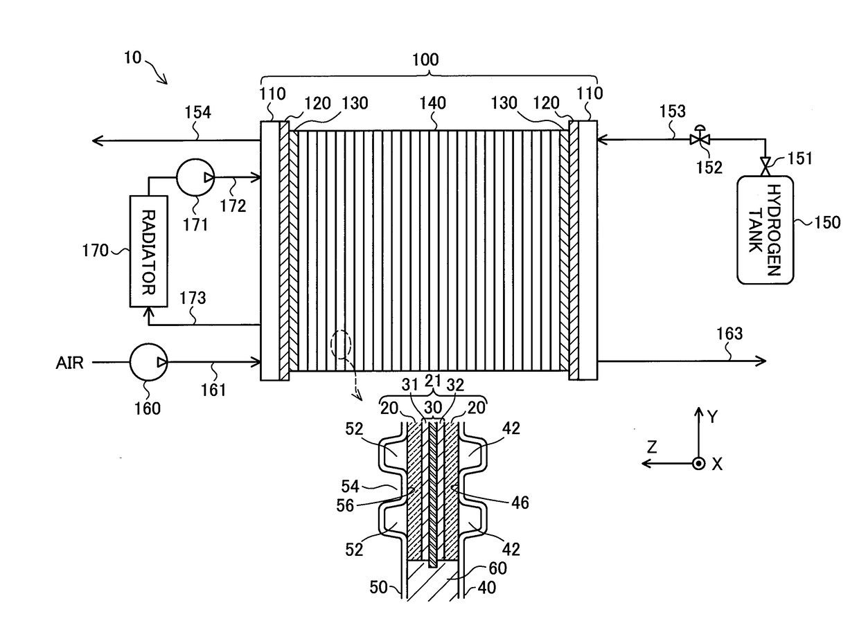
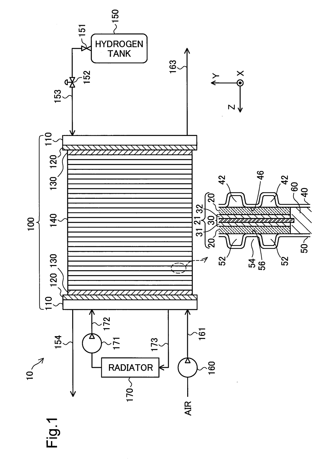
[0023]FIG. 1 is an explanatory view showing a schematic configuration of a fuel cell system 10 according to a first embodiment of the disclosure. The fuel cell system 10 is equipped with a fuel cell stack 100. The fuel cell stack 100 includes an end plate 110, an insulating plate 120, a current collector plate 130, a plurality of fuel-cell unit cells (hereinafter, abbreviated as ‘unit cells’) 140, another current collector plate 130, another insulating plate 120, and another end plate 110, as these are stacked in this order. A stacking direction Z of the unit cells 140 is a horizontal direction perpendicular to a vertical direction Y. A direction normal to the drawing sheet and perpendicular to both the vertical direction Y and the stacking direction Z is a horizontal direction X.

[0024]Hydrogen is supplied as an anode gas to the fuel cell stack 100 from a hydrogen tank 150, in which high-pressure hydrogen is stored, via a shutoff valve 151, a regulator 152, and piping 153. Anode gas...

second embodiment

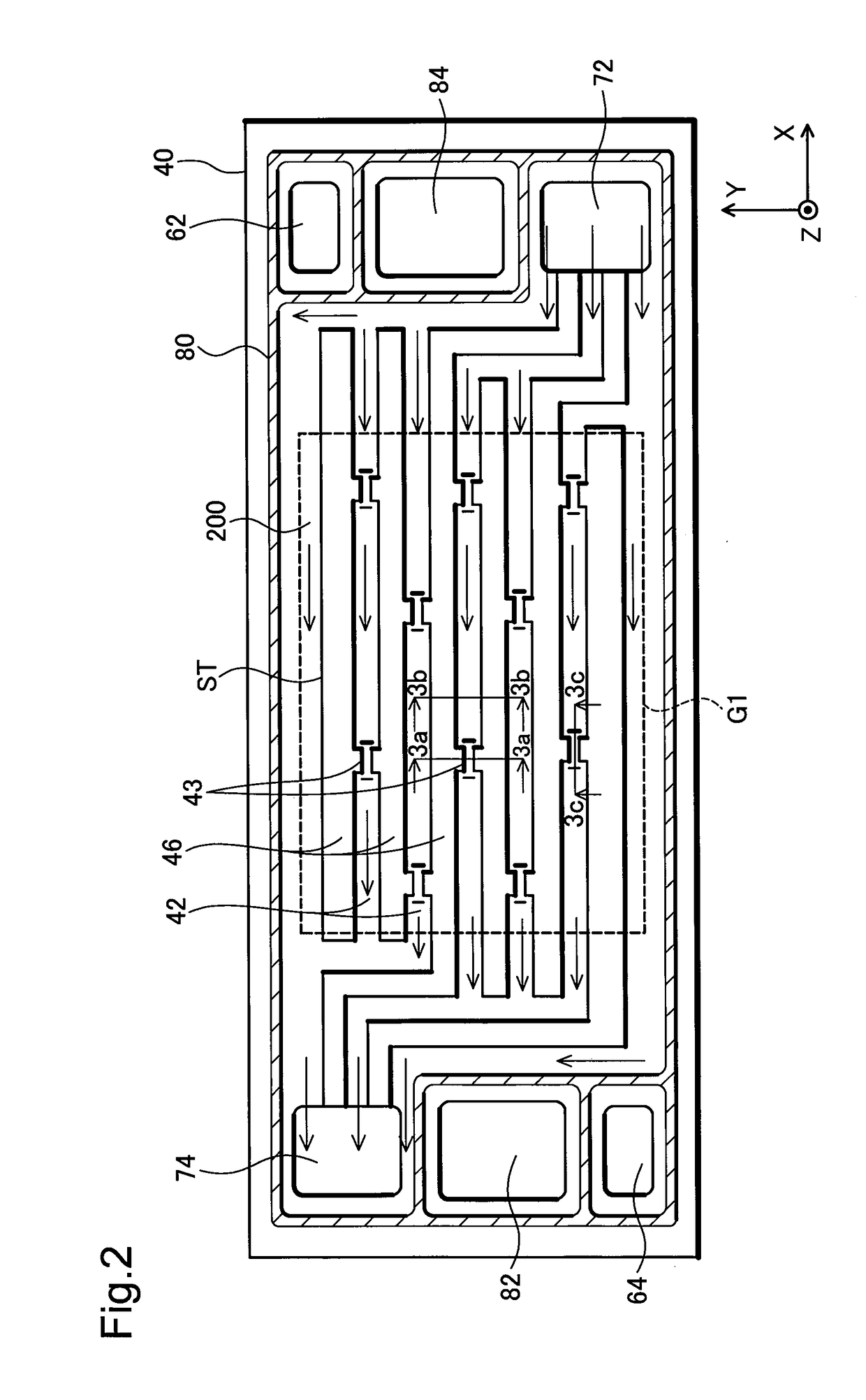
[0053]FIG. 8 is a schematic plan view of a cathode-side separator 40a as viewed from the MEGA 21 side in a second embodiment. This embodiment differs from the first embodiment shown in FIG. 2 only in the shape of constricting portions 43a, the rest of the structure being similar to that of the first embodiment.

[0054]FIGS. 9A-9B are sectional views of the cathode gas flow paths 42 in the second embodiment. FIG. 9A is a sectional view taken along the line 9a-9a of a constricting portion 43a shown in FIG. 8, and FIG. 9B is a sectional view of a portion of the cathode gas flow path 42 other than the constricting portion 43a taken along the line 9b-9b shown in FIG. 8. A flow path cross-sectional area S43a of the constricting portion 43a is smaller than a flow path cross-sectional area S42 of the portion of the cathode gas flow path 42 other than the constricting portion 43a. A flow-path height Hs of the constricting portion 43a in the stacking direction Z is smaller than a flow-path heig...


PUM

PropertyMeasurementUnit
heightaaaaaaaaaa
poweraaaaaaaaaa
shapesaaaaaaaaaa

Abstract

A fuel-cell unit cell comprises: a membrane electrode and gas diffusion layer assembly; a cathode-side separator made of a press-molded plate, the cathode-side separator forming a plurality of cathode gas flow paths and non-flow-path portions therebetween on a cathode-side surface of the membrane electrode and gas diffusion layer assembly; and an anode-side separator made of a press-molded plate, the anode-side separator forming a plurality of anode gas flow paths and non-flow-path portions therebetween on an anode-side surface of the membrane electrode and gas diffusion layer assembly. At least one gas flow path among the plural cathode gas flow paths and the plural anode gas flow paths includes a constricting portion that is configured to reduce a flow-path height in a stacking direction of the fuel-cell unit cells as well as to reduce a flow path cross-sectional area of the gas flow path. When projected and observed along the stacking direction, the plural cathode gas flow paths and the plural anode gas flow paths are configured to have mutually different two-dimensional shapes, there exist intersect positions at which the cathode gas flow paths and the anode gas flow path intersect each other, and the constricting portion is provided at a position other than the intersect positions.

Description

CROSS REFERENCE TO RELATED APPLICATIONS[0001]This application claims priority to Japanese Patent Application No. 2016-125353 filed on Jun. 24, 2016, the entire contents of which are incorporated by reference herein.BACKGROUNDField[0002]The present disclosure relates to a fuel-cell unit cell.Related Art[0003]Generally, a fuel cell has a fuel cell stack in which a plurality of unit cells are stacked. Each unit cell has a membrane electrode and gas diffusion layer assembly with a power generation region therein, and two separators for sandwiching the membrane electrode and gas diffusion layer assembly therebetween. The membrane electrode and gas diffusion layer assembly is formed such that one electrolyte membrane is sandwiched between two electrode catalyst layers, which are further sandwiched between two gas diffusion layers. The power generation region is a region coincident with a region over which the two electrode catalyst layers overlap with each other. On one surface of each se...

Claims


Application Information

Patent Timeline
Patent Type & Authority Applications(United States)
IPC IPC(8): H01M8/1004H01M8/026H01M8/0247
CPCH01M8/1004H01M8/0247H01M8/026H01M8/0254Y02E60/50
Inventor HAYASHI, DAISUKEIDA, ATSUSHISHIBATA, KAZUNORINONOYAMA, NOBUAKIKURITA, SHUJI
Owner TOYOTA JIDOSHA KK
Why Eureka
Try Eureka