Beamforming method based on arrays of microphones and corresponding apparatus

a technology of arrays and microphones, applied in the field of beamforming, can solve the problems of inability to design virtual microphones and inability to maintain continuous steering,

Active Publication Date: 2017-12-28
STMICROELECTRONICS SRL
View PDF1 Cites 122 Cited by
  • Summary
  • Abstract
  • Description
  • Claims
  • Application Information

AI Technical Summary

Benefits of technology

[0038]Various embodiments refer to beamforming apparatuses and likewise to a computer program product that can be loaded into the memory of at least one computer (e.g., a terminal in a network) and comprises portions of software code suitable for carrying out the steps of the method when the program is run on at least one computer. As used herein, the aforesaid computer program product i

Problems solved by technology

In general it is not possible to design the Virtual Microphone polar pattern with the main lobe aiming at a direction different from angle ψm at which each of the M microphones is set, with 1≦m≦M.
Although arbitrary order Differential Microphone Array (DMA) based systems with Virtual Microphones steerable

Method used


Image

  • Beamforming method based on arrays of microphones and corresponding apparatus
  • Beamforming method based on arrays of microphones and corresponding apparatus
  • Beamforming method based on arrays of microphones and corresponding apparatus

Examples


embodiment 100

[0113]Thus, the beamforming procedure described so far, an embodiment 100 of which is indicated in the flow diagram shown in FIG. 14, starting from a plurality of omni-directional microphones, M1 . . . Mm, for instance M1 . . . M4 in FIG. 8, arranged as an array with respect to a reference point, such as ULA or UCA, where are acquired in a step 110 microphone signals X1 . . . XM, issued by said plurality of microphones which are combined, in a step 120, to obtain at least a pair of Virtual Microphones, such as Virtual Microphones V1 and V2, having respective patterns of radiation with a same origin corresponding to the reference point O of the array and rotated at different pattern direction angles, defining a separation angle ρ, so that a circular sector CS of corresponding aperture is defined between said different pattern direction angles. In general from M microphone signals X1 . . . XM can be obtained N Virtual Microphones V1 . . . VN, from which one or more pair of Virtual Mic...

embodiment 200

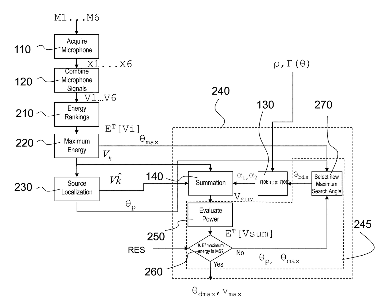
[0124]With reference to FIG. 15, which shows a flow diagram representing an embodiment 200 of a source localization procedure, thus it is provided to acquire in a step 110 the analog microphone signals from the microphones M1 . . . M6 through analog to digital conversion obtaining digital microphone signal X1 . . . X6.

[0125]In a step 120 Virtual Microphones, in particular six Virtual Microphones V1 . . . V6 are obtained, combining the signals X1 . . . X6 using the linear DMA theory, as described with reference to FIG. 14, i.e., applying a delay for instance to the signal X1 before summing the microphone signals, X1 and X4, which are signals of microphones placed at a given distance d, i.e., the diameter of the circumference of the array 31. Virtual Microphone V1, as mentioned, is obtained by combining digital signals X1 and X4, Virtual Microphone V2 is obtained by combining digital signals X2 and X5, Virtual Microphone V3 is obtained by combining digital signals X3 and X6. Virtual M...


PUM


Abstract

A beamforming method employs a plurality of microphones arranged in an array with respect to a reference point. The method includes acquiring microphone signals from the microphones and combining the microphone signals (x1 . . . xM) to obtain Virtual Microphones, combining the microphone signals to obtain a pair of directional Virtual Microphones having respective signals determining respective patterns of radiation with a same origin corresponding to the reference point and rotated at different pattern direction angles, defining a separation angle between them, obtaining a sum radiation signal of a sum Virtual Microphone with a sum radiation pattern, associating a respective weight to the signals of the pair of directional Virtual Microphones, obtaining respective weighted signals of radiation and summing the weighted signals, computing respective weights as a function of a determined pattern direction angle of the pattern of radiation of the pair of directional Virtual Microphones and of the separation angle.

Description

BACKGROUNDTechnical Field[0001]The present description relates to beamforming based on a plurality of microphones arranged in an array or arrays with respect to a reference point, including acquiring microphone signals issued by said plurality of microphones, which may be preferably applied to sound source localization.Description of the Related Art[0002]It is very well known to use arrays of microphones to perform sound, or acoustic, source localization, i.e., locating a sound source given measurements of the sound field, which in particular are obtained by such microphones.[0003]It is also known to use signal processing modules such as DSP (Digital Signal Processing) modules to process the signals from each of the individual microphone array elements to create one or more Virtual Microphones (VMIC).[0004]Virtual Microphones (VMIC) are therefore a combination of filtered versions of the signals sensed by an array of microphones arranged in a particular spatial geometry.[0005]Virtua...

Claims


Application Information

Patent Timeline
IPC IPC(8): H04R3/00H04R1/40
CPCH04R3/005H04R2201/403H04R1/406H04R2430/21
Inventor BERNARDINI, ALBERTOD'ARIA, MATTEOSANNINO, ROBERTO
Owner STMICROELECTRONICS SRL
Why Eureka
Try Eureka