Automatic safety device and method for a stove

a safety device and stove technology, applied in the field of automatic safety devices and methods for stoves, can solve the problems of stoves or burners that cannot be manually shut off, and the risk of fire igniting is significantly higher

Active Publication Date: 2018-01-04
INIRV LABS INC
View PDF5 Cites 11 Cited by
  • Summary
  • Abstract
  • Description
  • Claims
  • Application Information

AI Technical Summary

Benefits of technology

[0071]In some examples, the non-transitory computer-readable storage medium stores further program code instructions that, when executed, cause the computing device to further: receive a user selection from a user interface; determine a user control signal from the user selection; and send the user control signal to the controlle...

Problems solved by technology

The risks of a fire igniting are significantly higher during unattended use of a stove ...

Method used


Image

  • Automatic safety device and method for a stove
  • Automatic safety device and method for a stove
  • Automatic safety device and method for a stove

Examples


first embodiment

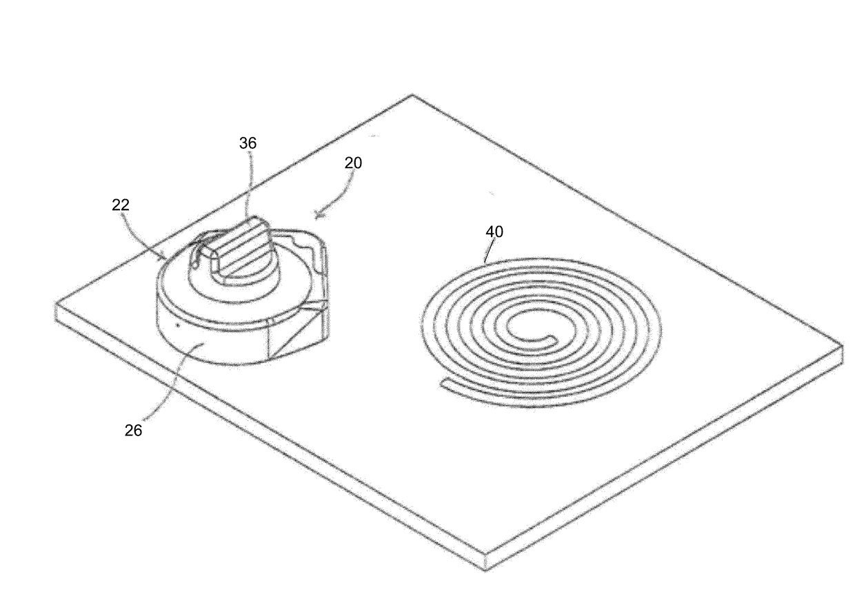
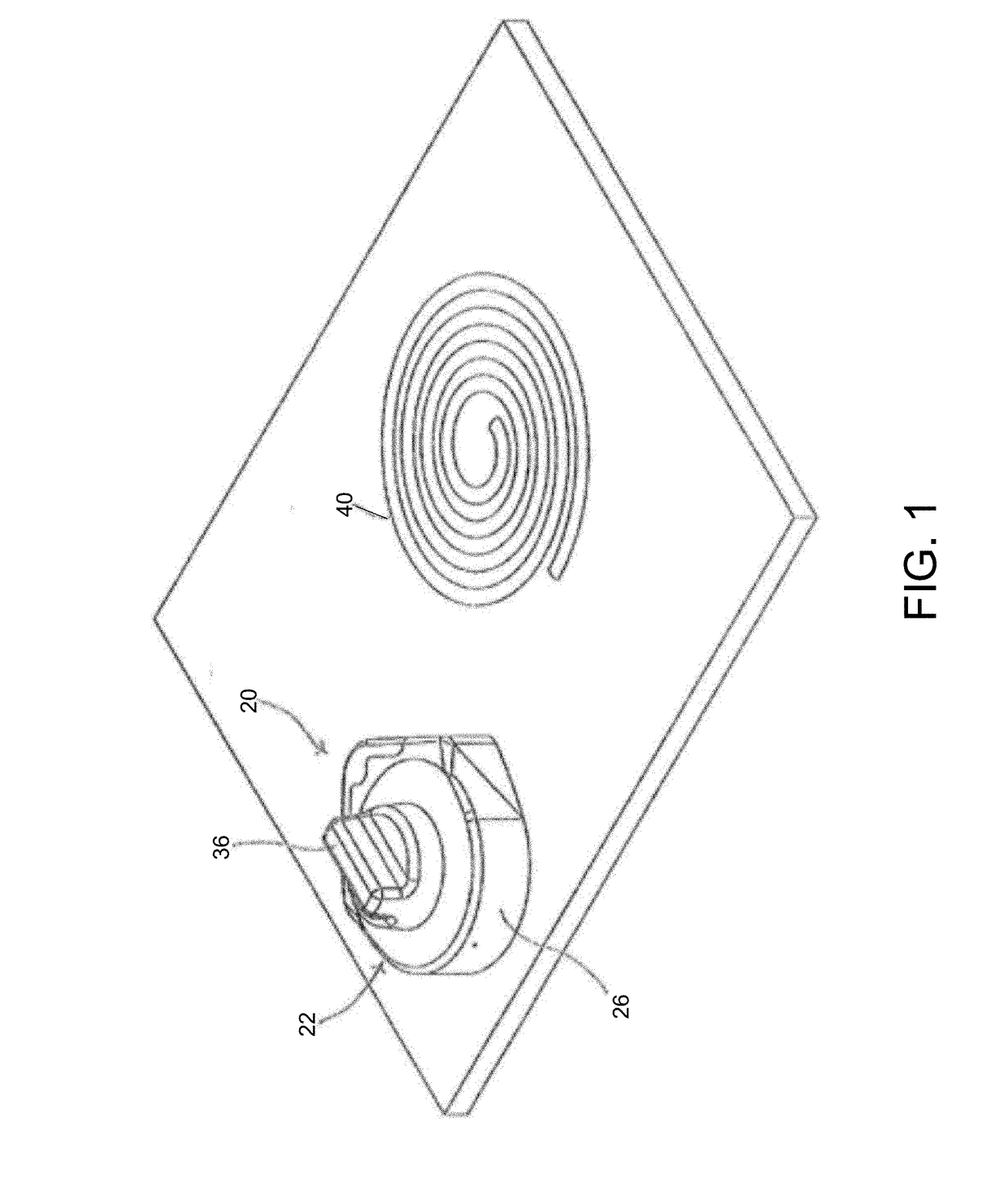
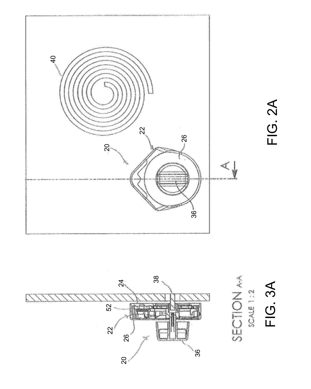
[0141]a stove knob safety device for operational control of a stove top burner is shown in FIGS. 1, 2A, 3A, and 4A-4C and generally designated 20. The stove top may comprise a plurality of burners. Each of the plurality of burners may also be controlled by a safety device 20. Additionally, the safety device 20 may also be configured for operational control of a single burner, not a part of stove top, such as a hot plate or other device. The safety device 20 comprises a housing 22 including a base member 24 and an outer member 26, a bracket 28 disposed in the housing 22 for supporting a gear train, an electric motor 30, and a two-piece adaptor 33 and 34 for a control knob 36 engaged with an operational shaft 38 of the burner 40 via the adaptor. The housing 22 further accommodates a switch, a power source and a controller. The controller is programmed to actuate the motor 30 to rotate the control knob 36 to the Off position upon occurrence of an event. As described below, the safety d...

second embodiment

[0146]a safety device for operational control of a stove top burner is shown in FIGS. 2B, 3B, and 4D-4F and generally designated 400. As shown, safety device 400 may comprise a complete knob for operating an operational shaft of a burner such that safety device 400 may be embodied as an after-market device which is configured to replace an original knob of a stove or may be integrated into a stove top as original knob equipment during manufacture of the stove. Safety device 400 may be turned manually by a user to turn an operational shaft of a burner to an On position such that power is supplied to the burner. As shown, the plurality of members of safety device 400 including the outer or housing members, may form a knob.

[0147]In addition to the features described herein, safety device 400 may include any or all of the features of safety device 20 or safety device 100 described herein. In some examples, safety device 400 may function as a replacement knob or a knob for controlling th...


PUM


Abstract

Device and method are described for operational control of a knob on a stove or range. In some examples, a safety device, a sensor relay device, and method are described for automatically positioning an operational shaft of a burner to an Off position such that the power supplied to the burner is terminated upon the occurrence of a safety event.

Description

CROSS-REFERENCE TO RELATED APPLICATIONS[0001]This application incorporates U.S. Provisional Application No. 62 / 356,864 filed Jun. 30, 2016, U.S. Provisional Application No. 62 / 379,671, filed Aug. 25, 2016, U.S. Provisional Application No. 62 / 404,522, filed Oct. 5, 2016 and U.S. Provisional Application No. 62 / 447,181, filed Jan. 17, 2017 by reference herein in their entirety.FIELD OF THE INVENTION[0002]An automated safety device is described for operational control of a knob on a stove or range and, more particularly, a safety device and method is described for automatically positioning an operational shaft, such as for a burner, to an Off position for terminating power to the burner upon the occurrence of a safety event.BACKGROUND OF THE INVENTION[0003]A large number of residential and commercial fires originate in the kitchen during cooking. The stove top burner is a common source for ignition of these fires, for example, as overheated cooking oils or greases can easily ignite. The...

Claims


Application Information

Patent Timeline
IPC IPC(8): F24C7/08H05B1/02F24C15/10
CPCF24C7/088H05B1/0266F24C15/103F24C7/082F24C3/12
Inventor BABU, RANJITHIYER, AKSHITABAILEY, PATRICK THOMASMCNEIL, RAESHONLOSAW, JEREMY
Owner INIRV LABS INC
Why Eureka
Try Eureka