Image heating apparatus and image forming apparatus

a heating apparatus and image technology, applied in the field of image forming apparatus, can solve the problems of fixing failure or gloss reduction, and the possibility of a power saving effect may decline, and achieve the effect of suppressing fixing failure, gloss reduction, and power saving

Active Publication Date: 2018-01-04
CANON KK
View PDF6 Cites 33 Cited by
  • Summary
  • Abstract
  • Description
  • Claims
  • Application Information

AI Technical Summary

Benefits of technology

[0005]An object of the present invention is to provide a technique which enables a further power saving effect to b

Problems solved by technology

As a result, there is a possibility that fixing failure or gloss decrease may occur in a vicinity of an image end section on a side of a boundary position in the image heating section adjacent to the non-image heating section.
However, with the system disclosed in Japanese Patent Application L

Method used


Image

  • Image heating apparatus and image forming apparatus
  • Image heating apparatus and image forming apparatus
  • Image heating apparatus and image forming apparatus

Examples


example 1

[0026]1. Configuration of Image Forming Apparatus

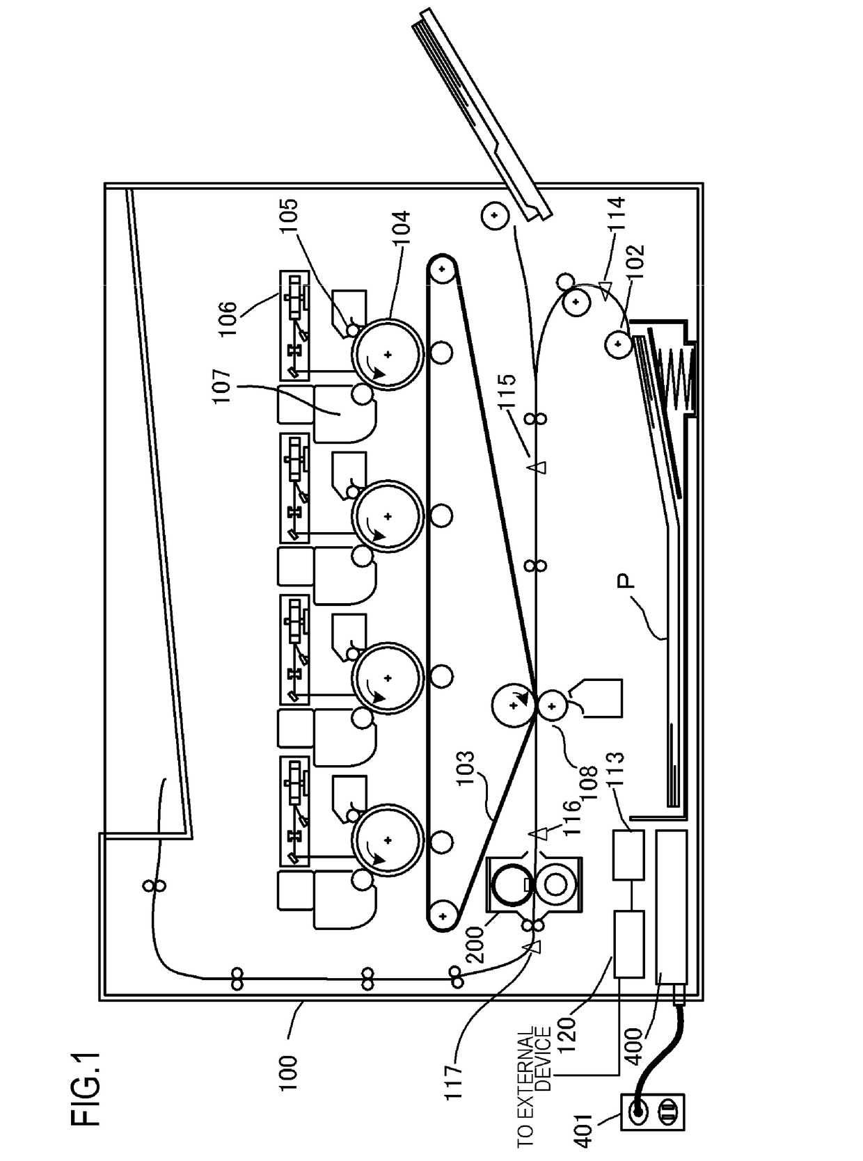
[0027]FIG. 1 is a configuration diagram of an image forming apparatus adopting an electrophotographic system according to an example of the present invention. Examples of image forming apparatuses to which the present invention is applicable include copying machines, printers, and the like which utilize an electrophotographic system or an electrostatic recording system, and a case where the present invention is applied to a laser printer will be described below.

[0028]An image forming apparatus 100 includes a video controller 120 and a control portion 113. As an acquiring portion which acquires information on an image formed on a recording material, the video controller 120 receives and processes image information and print instructions transmitted from an external apparatus such as a personal computer. The control portion 113 is connected to the video controller 120 and controls respective units constituting the image forming apparatu...

example 2

[0096]Since configurations of the image forming apparatus, the image heating apparatus, the heater, and the heater control circuit according to Example 2 of the present invention are similar to those of Example 1, a description thereof will be omitted. Differences of Example 2 from Example 1 will now be mainly described. Matters not described in Example 2 are similar to those described in Example 1.

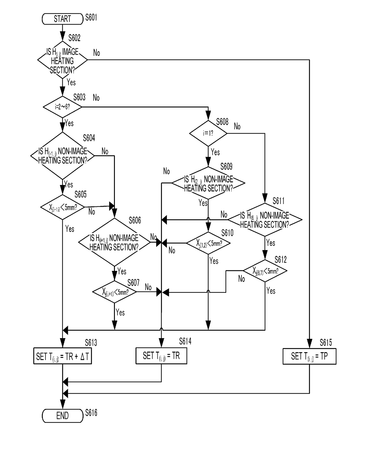
[0097]Example 2 differs from Example 1 in that the predetermined amount ΔT is changed in accordance with image density. Specifically, a toner amount conversion value representing a conversion of image density of each color obtained from CMKY image data received by the video controller 120 from a host computer into a toner amount is calculated for each image heating section. In addition, with respect to a heating section H(i, j) satisfying both the condition M1 and the condition M2 according to Example 1, control is performed to change the predetermined amount ΔT in accordance with a maxim...


PUM


Abstract

An image heating apparatus includes a first heat generating element; a second heat generating element which is arranged adjacent to the first heat generating element in a longitudinal direction; and a control portion which controls power supplied to the first and second heat generating elements. When an image exists in a second region on the recording material heated by the second heat generating element but an image does not exist in a first region on the recording material heated by the first heat generating element, the control portion sets a control temperature of the second heat generating element when heating the second region, in accordance with a distance between an end section of the image in the second region and a boundary of the first region and the second region.

Description

BACKGROUND OF THE INVENTIONField of the Invention[0001]The present invention relates to an image forming apparatus such as a copying machine or a printer which uses an electrophotographic system or an electrostatic recording system. The present invention also relates to an image heating apparatus such as a fixing unit mounted on an image forming apparatus, and a gloss applying apparatus which heats the toner image fixed on a recording material again in order to improve the gloss level of the toner image.Description of the Related Art[0002]A system which selectively heats an image portion formed on a recording material in an image heating apparatus such as a fixing unit and a gloss applying apparatus used in an electrophotographic image forming apparatus (hereinafter, an image forming apparatus) such as a copying machine or a printer has been proposed in order to meet demands for power saving (Japanese Patent Application Laid-open No. H6-95540). In this system, a plurality of divided...

Claims


Application Information

Patent Timeline
IPC IPC(8): G03G15/20
CPCG03G15/2078G03G15/205G03G15/2007G03G2215/00805G03G15/2042G03G2215/209G03G15/2053G03G15/2039
Inventor SAKO, MASATOIWASAKI, ATSUSHI
Owner CANON KK
Why Eureka
Try Eureka