Communication control device, communication system, and communication control method

Active Publication Date: 2018-01-04
RICOH KK
View PDF1 Cites 2 Cited by
  • Summary
  • Abstract
  • Description
  • Claims
  • Application Information

AI Technical Summary

Benefits of technology

[0008]According to one aspect of the present invention, A communication control device is configured to control data communication between terminals using a communication network. The communication control device include: a status-information acquiring unit configured to acquire respective pieces of status information which represent operating states of the terminals; a reception-information acquiring unit configured to acquire respective pieces of reception information which repre

Problems solved by technology

When data communication is performed among terminals by using a communication network, the volume of data that can be transmitted at one time is limited by the bandwidth of the communication network (the network bandwidth).
Therefore, when data of a high-quality video and voice or the like is transmitted/received among the terminals, there is a problem that according to the state of the network bandwidth, a delay or packet loss m

Method used


Image

  • Communication control device, communication system, and communication control method
  • Communication control device, communication system, and communication control method
  • Communication control device, communication system, and communication control method

Examples


Example

First Embodiment

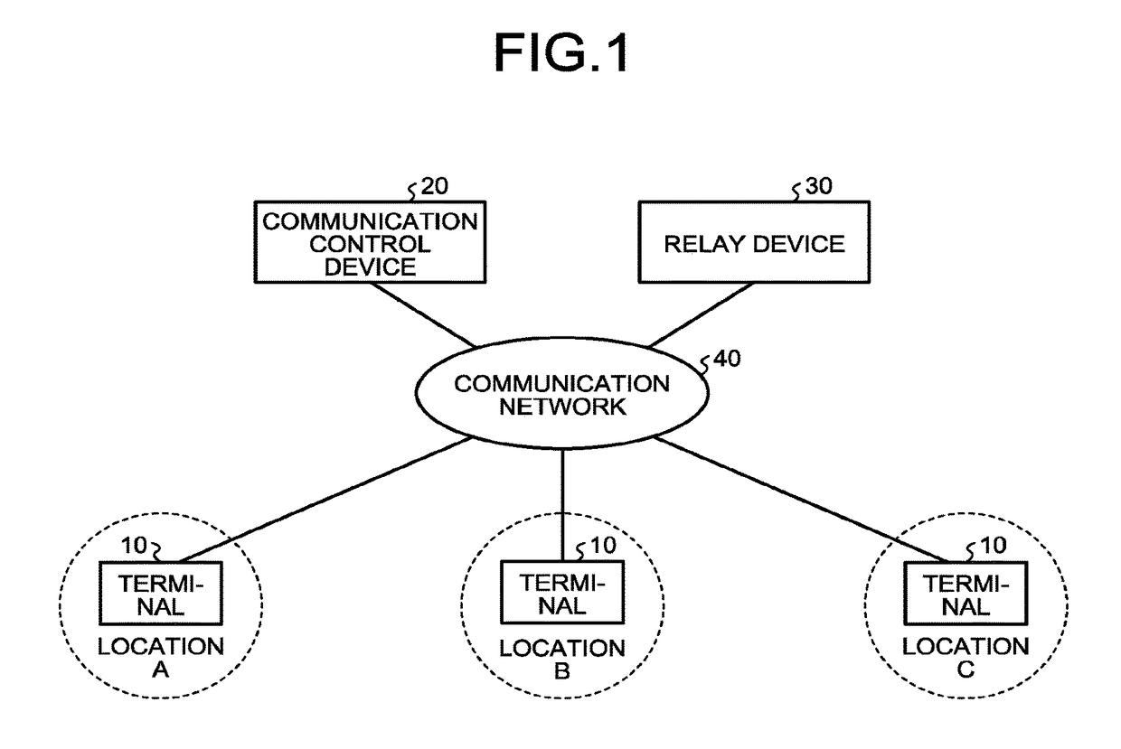
[0033]FIG. 1 is a schematic configuration diagram of a video conference system according to a first embodiment. As illustrated in FIG. 1, the video conference system according to the present embodiment has a configuration in which terminals 10 at different locations that participate in communication using the video conference system, a communication control device 20, and a relay device 30 are connected via a communication network 40. The communication network 40 is constructed of a single or combination of network technologies, such as the Internet and a local area network (LAN). This communication network 40 can include not only wired part but also wireless part where communication is performed using wireless technology, such as Wireless Fidelity (WiFi) and Bluetooth™.

[0034]The number of the terminals 10 connected to the communication network 40 corresponds to the number of locations that participate in the communication. In the present embodiment, as an example, a...

Example

Second Embodiment

[0101]FIG. 15 is a schematic configuration diagram of a video conference system according to a second embodiment. As illustrated in FIG. 15, the video conference system according to the present embodiment further includes a management device 60 in addition to the configuration of the video conference system according to the above-described first embodiment (see FIG. 1). In the following, only the difference from the first embodiment is described.

[0102]The management device 60 is a server computer that manages the overall video conference system according to the present embodiment. For example, the management device 60 performs an authentication process when each terminal 10 logs in to the system, reception of a notification of holding or close of communication, management of communication currently being held, management of the state of each terminal 10, etc. A hardware configuration of the management device 60 is the same as, for example, that of the communication ...

Example

Third Embodiment

[0113]FIG. 18 is a schematic configuration diagram of a video conference system according to a third embodiment. As illustrated in FIG. 18, the video conference system according to the present embodiment is an example in which communication is performed between two locations: Location A and Location B; the above-described relay device 30 is unnecessary. That is, in the present embodiment, the terminal 10 at Location A and the terminal 10 at Location B directly transmit / receive data between them without involving the relay device 30.

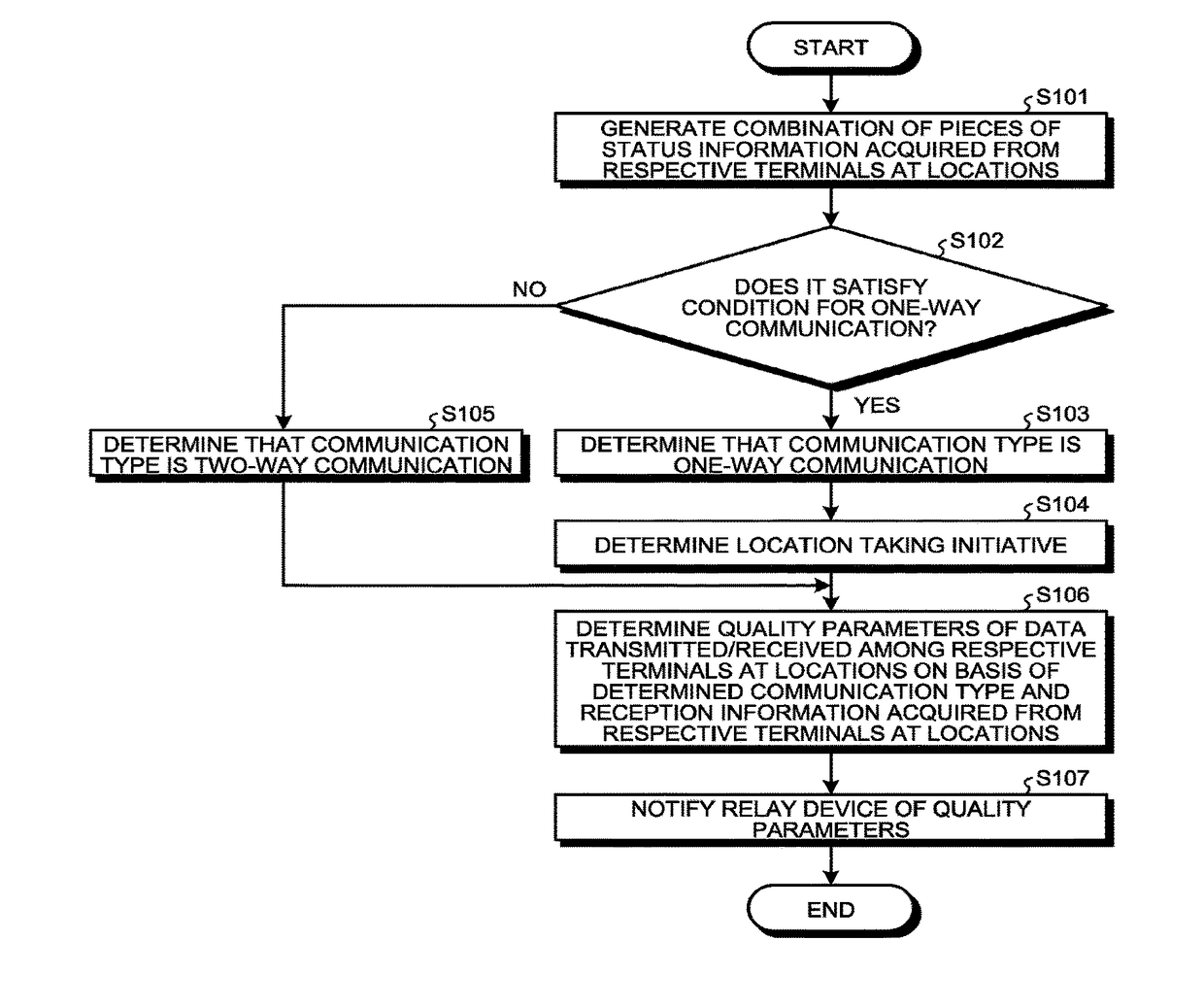
[0114]Also in the present embodiment, the communication control device 20 determines the type of communication performed between the two locations: Location A and Location B on the basis of a combination of status information acquired from the terminal 10 at Location A and status information acquired from the terminal 10 at Location B. Then, quality parameters of data transmitted / received between the two terminals 10 are determined on the ...


PUM


Abstract

A communication control device is configured to control data communication between terminals using a communication network. The communication control device include: a status-information acquiring unit configured to acquire respective pieces of status information which represent operating states of the terminals; a reception-information acquiring unit configured to acquire respective pieces of reception information which represent states of the communication network when the terminals have received data; a communication determining unit configured to determine a type of communication on the basis of a combination of pieces of status information of multiple terminals that participate in the same communication; and a quality control unit configured to control quality of data that each terminal transmits or receives on the basis of the determined type of communication and the acquired reception information.

Description

CROSS-REFERENCE TO RELATED APPLICATIONS[0001]The present application is a continuation application of International Application No. PCT / JP2016 / 001525, filed Mar. 16, 2016, which claims priority to Japanese Patent Application No. 2015-056129, filed Mar. 19, 2015. The contents of these applications are incorporated herein by reference in their entirety.BACKGROUND OF THE INVENTION1. Field of the Invention[0002]The present invention relates to a communication control device, a communication system, and a communication control method.2. Description of the Related Art[0003]As one of communication systems that realize communication among users using a communication network such as the Internet, a video conference system has been in widespread use. The video conference system realizes a remote conference among geographically distant locations by causing respective terminals at the locations, each connected to a communication network, to perform data communication among the terminals in such...

Claims


Application Information

Patent Timeline
IPC IPC(8): H04L29/06
CPCH04L65/1086H04L65/80H04L65/403H04N7/15H04N21/2662H04L12/6418H04N7/147H04M3/2227H04M3/567
Inventor IMAI, TAKUYAMORITA, KENICHIRONAGAMINE, SHOH
Owner RICOH KK
Why Eureka
Try Eureka