
Electromagnetic shielding tube and electromagnetic shielding structure

a technology of electromagnetic shielding and electromagnetic shielding, applied in the direction of flexible conductors, insulating bodies, contact contact member materials, etc., can solve the problems of difficulty in maintaining the predetermined internal diameter, weight, and possible problems, and achieve the effect of reducing the effect and increasing the contact resistan

Active Publication Date: 2018-01-04
FURUKAWA ELECTRIC CO LTD +1
View PDF3 Cites 4 Cited by
  • Summary
  • Abstract
  • Description
  • Claims
  • Application Information

AI Technical Summary

Benefits of technology

The patent text describes an electromagnetic shielding tube designed to prevent differences in physical properties between its inner layer and metal layer. The tube includes an inner layer made of resin, a metal layer formed on the inner layer's outer periphery, and an outer layer made of resin on the metal layer's outer periphery. A terminal processed portion is provided on an exposed portion of the metal layer to mitigate the impact of changes in temperature on the inner layer. The technical effect is to provide an improved electromagnetic shielding tube that prevents physical property differences between layers.

Problems solved by technology

With such cable protecting tubes, problems may occur such as the influence of noise generated by the cable housed in the protecting tube or the influence of external noise on the cable inside the protecting tube.
However, in this case, noises generated by the cable disrupt the radio and the like and, therefore, shielding is necessary.
However, the metal tube in Japanese Unexamined Patent Application Publication No. 2007-81158A is made of metal and, thus, has a problem of weight.
If the thickness of the metal tube is decreased to reduce the weight, the bent portion may collapse and flatten when bending the tube, thereby making it difficult to maintain the predetermined internal diameter.
Additionally, since a certain thickness is required, a large processing machine is needed for the bending.
As such, workability during the product shaping process is not always good.
However, with the metal tubes described above, there is a high possibility of dents being formed when flying rocks or the like collide with the outer surface of the tube.
Additionally, costs increase when using stainless steel, such as in Japanese Unexamined Patent Application Publication No. 2007-81158A.
Moreover, with such protecting tubes, not only is there a possibility of water becoming adhered to the outside of the tube, but there is also a possibility of water becoming adhered to the inside the tube due to condensation and the like.
Consequently, forming a stainless layer only on the outermost layer does not completely solve the problem of corrosion.
H09-298382A, there are problems with peeling, corrosion, and the like of the plating.
With electric automobiles in particular, due to the fact that substantial levels of noise are generated, there is a possibility of other electrical components being affected.
However, with the method described in Japanese Unexamined Patent Application Publication No.
H09-298382A in which a metal layer is formed on a corrugated tube made of resin using an electroless plating method, there is a limit to the shielding properties that can be obtained from the thickness of the metal layer.
Consequently, it is difficult to achieve both high shielding properties and adhesion between the metal layer and the resin layer.
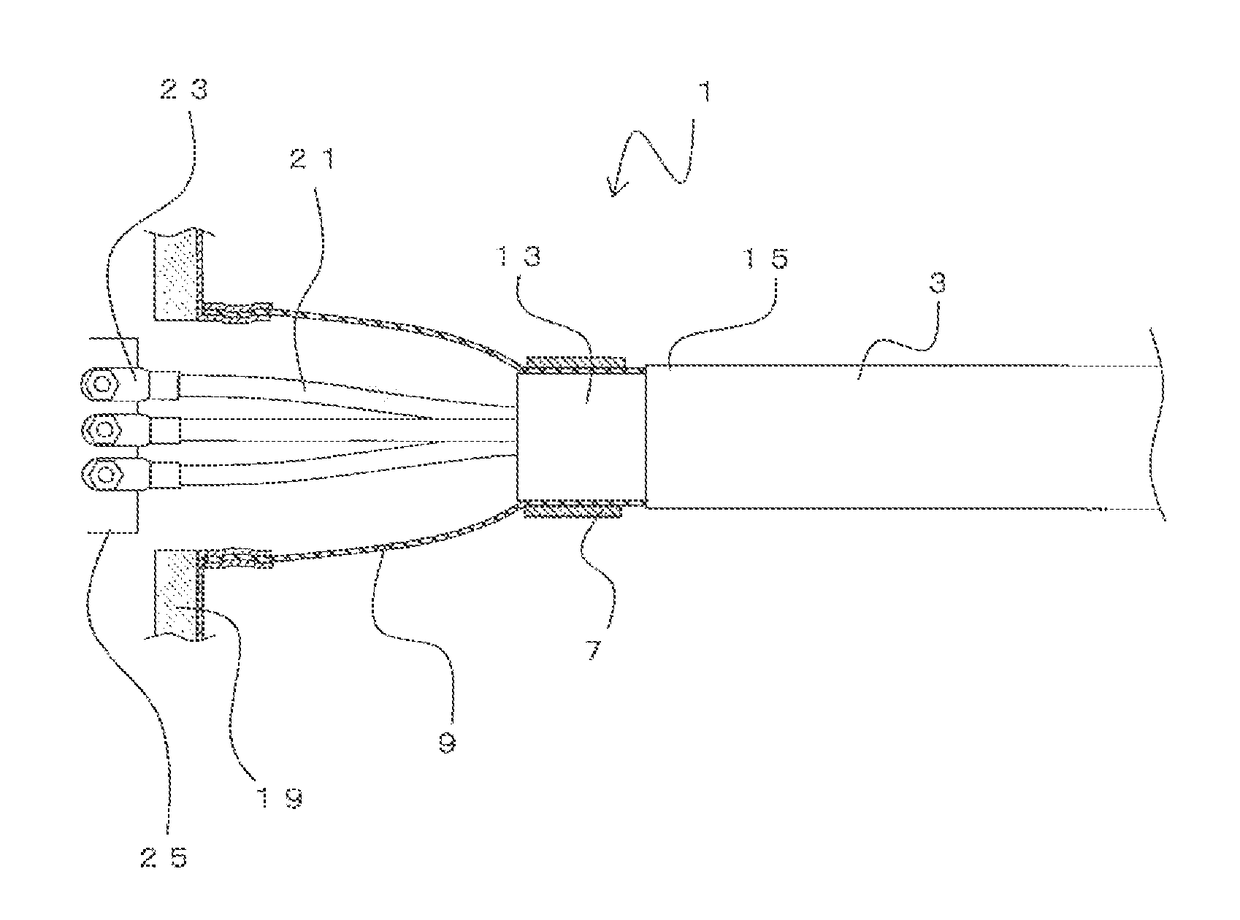
Thus, due to the contraction of the inner layer, contact between the metal layer and the flexible conductor connected to the outer periphery of the metal layer may worsen and contact resistance at the connection portion may increase.
Furthermore, the flexible conductor connected to the outer periphery of the metal layer may fall off due to reductions in the diameter of the metal layer.
Additionally, when the inner layer of the composite tube contracts due to changes in the temperature, the repulsive force from the metal layer generated when tightening the ring member on the metal layer weakens.
As a result, the flexible conductor connected to the outer periphery of the metal layer may fall off.

Method used


Image

  • Electromagnetic shielding tube and electromagnetic shielding  structure
  • Electromagnetic shielding tube and electromagnetic shielding  structure
  • Electromagnetic shielding tube and electromagnetic shielding  structure

Examples


second embodiment

[0111]Next, a second embodiment will be described. FIG. 4 is a cross-sectional view illustrating an electromagnetic shielding tube 3a. Note that, in the description below, constituent elements which serve the same functions as in the configuration illustrated in FIGS. 1A, 1B, and 2 are assigned the same reference numerals as in FIGS. 1A, 1B, and 2, and redundant descriptions of those constituent elements are foregone.

[0112]The electromagnetic shielding tube 3a is substantially the same as the electromagnetic shielding tube 3, with the exception of the terminal processed portion (the stress transmission suppressing structure). In the electromagnetic shielding tube 3a, a terminal processed portion 50a, namely a separated portion 27, is provided between the inner layer 11 and the metal layer 13. The separated portion 27 is a portion where the outer surface of the inner layer 11 and the inner surface of the metal layer 13 are separated and are not joined to each other.

[0113]Note that it...

third embodiment

[0118]Next, a third embodiment will be described. FIG. 5A is a perspective view of an electromagnetic shielding tube 3b; FIG. 5B is a cross-sectional view perpendicular to a length direction of the electromagnetic shielding tube 3b, and is a cross-sectional view taken along line C-C of FIG. 5A.

[0119]As described above, the outer layer 15 is peeled exactly a predetermined length from the end portion of the electromagnetic shielding tube 3b. That is, the metal layer 13 is exposed exactly a predetermined range at the end portion of the electromagnetic shielding tube 3b. A terminal processed portion 50b, namely an uneven portion 29, is formed on at least a portion of the exposed portion of the metal layer 13. The uneven portion 29 is a fine uneven shape formed on the outer peripheral surface of the metal layer 13, and is formed on the entire periphery in the circumferential direction of the metal layer 13. Note that it is preferable that raised portions of the uneven portion 29 are posi...

fourth embodiment

[0128]Next, a fourth embodiment will be described. FIG. 7A is a perspective view illustrating an electromagnetic shielding tube 3f; FIG. 7B is a cross-sectional view perpendicular to a length direction of the electromagnetic shielding tube 3f, and is a cross-sectional view taken along line J-J of FIG. 7A. The electromagnetic shielding tube 3f is substantially the same as the electromagnetic shielding tube 3b, with the exception that the groove-like separated portion 5 of the electromagnetic shielding tube 3 described above is provided in the inner layer 11. The separated portion 5 is a structure for suppressing the transmission of stress caused by changes in temperature between the inner layer 11 and the metal layer 13. That is, in the electromagnetic shielding tube 3f, terminal processed portions 50f, namely the uneven portion 29 and the separated portion 5, are provided.

[0129]The same effects can be obtained in the fourth embodiment as in the third embodiment. Additionally, the te...


PUM


Abstract

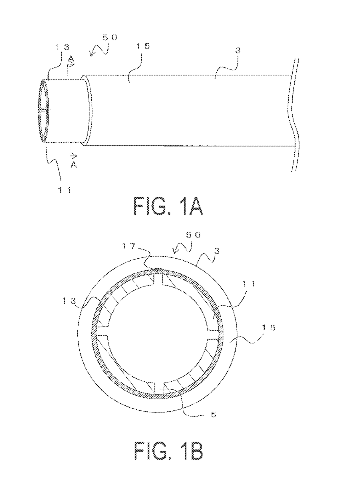
The outer layer is peeled exactly a predetermined length from the end portion of the electromagnetic shielding tube. That is, the metal layer is exposed exactly a predetermined range at the end portion of the electromagnetic shielding tube. A flexible conductor is connected to the exposed metal layer. A separated portion is provided in the inner layer. The separated portion is formed along the length direction of the electromagnetic shielding tube. Additionally, a depth of the separated portion is the same value as the thickness of the inner layer. As such, the inner surface of the metal layer is exposed at the separated portion. It is preferable that the separated portion be formed at a plurality of locations in the circumferential direction. The inner layer is divided into a plurality of sections in the circumferential direction by the separated portion. The separated portion is a terminal processed portion, which mitigates the effects caused by differences in the physical properties of the inner layer and the metal layer.

Description

TECHNICAL FIELD[0001]The present disclosure relates to an electromagnetic shielding tube and the like through which an electric wire is inserted, for use in, for example, an electric automobile.BACKGROUND[0002]Conventionally, metal tubes such as steel tubes or aluminum pipes, or corrugated tubes made of resin are used as cable protecting tubes. With such cable protecting tubes, problems may occur such as the influence of noise generated by the cable housed in the protecting tube or the influence of external noise on the cable inside the protecting tube. For example, in hybrid automobiles, in order to protect the cable that supplies three-phase AC output from the inverter to the drive motor, a protecting tube is provided in the lower portion and the like of the vehicle body so as to fit the shape of the vehicle body. However, in this case, noises generated by the cable disrupt the radio and the like and, therefore, shielding is necessary.[0003]Protecting tubes made have been proposed...

Claims


Application Information

Patent Timeline
IPC IPC(8): H05K9/00H01B17/62H01B7/04H01R4/28H01R4/60
CPCH05K9/0049H01B17/62H01B7/04H01R4/28H01R4/60H01R9/0518H01R11/12H02G15/068H05K9/0045H05K9/0084H05K9/0098
Inventor YAMASAKI, MASANORIYUASA, TATSUYASAKAI, KATSUTOSHINAGAO, AKIHIRO
Owner FURUKAWA ELECTRIC CO LTD
Learn More