
System and Method for Charging Vehicle Batteries

a charging system and battery technology, applied in the direction of battery/fuel cell control arrangement, electric devices, generators/motors, etc., can solve the problems of limited range of electric vehicles, no additional or backup charging systems,

Inactive Publication Date: 2018-01-11
TELLEZ ROBERT
View PDF0 Cites 33 Cited by
  • Summary
  • Abstract
  • Description
  • Claims
  • Application Information

AI Technical Summary

Benefits of technology

The patent text describes a charging system for electric vehicles that includes a movable member, such as a wheel or a wind-powered element. The system allows for improved charging of the vehicle's battery by providing an additional or backup charging system in case of failure of the vehicle's alternator or other electrical systems. The charging system can be used in various types of vehicles, such as golf carts, motorcycles, and electric cars. The system includes a fan that is powered by incoming air, which causes the fan to rotate and, in turn, generate electrical power for the vehicle. The technical effect of the patent is to provide an improved charging system for electric vehicles that ensures reliable charging even in the event of failure of the vehicle's alternator or other electrical systems.

Problems solved by technology

While an alternator provides a useful means for recharging the battery, such vehicles do not typically include any additional or backup charging system in the event of an alternator failure.
As a consequence, the range of a typical electric vehicle is limited to the distance the vehicle can be driven before the battery is discharged to the point where the battery can no longer provide sufficient electrical power for propelling the vehicle.

Method used


Image

  • System and Method for Charging Vehicle Batteries
  • System and Method for Charging Vehicle Batteries
  • System and Method for Charging Vehicle Batteries

Examples


Embodiment Construction

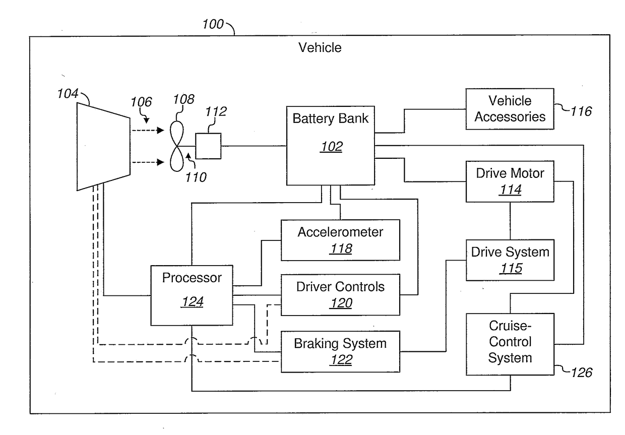
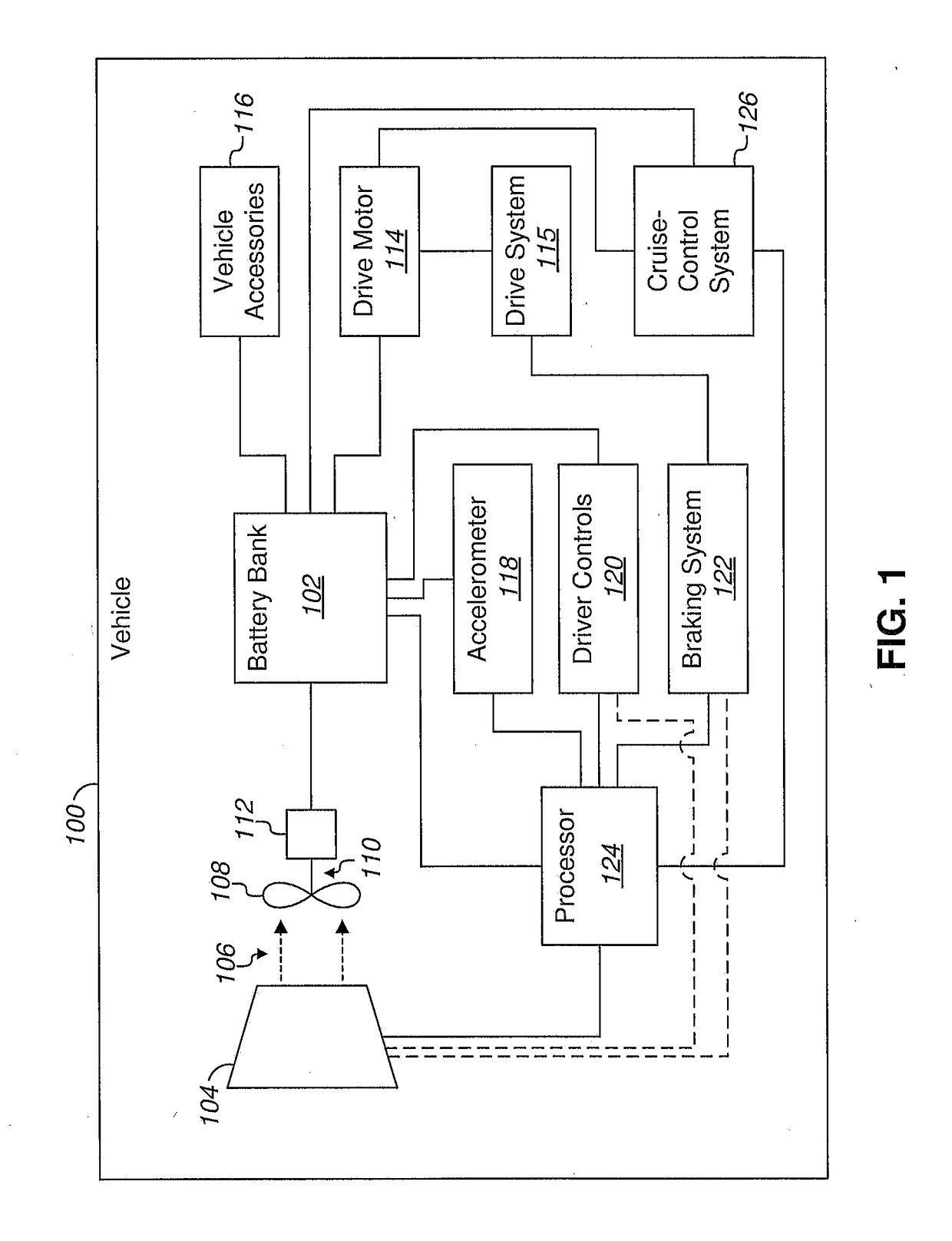
[0016]Referring to FIG. 1 in the drawings, a block diagram is shown of a vehicle 100, which can be any type of vehicle. Examples of vehicle types include golf carts, motorcycles, all-terrain vehicles (ATVs), cars, trucks, vans, and sport utility vehicles. It will be appreciated that vehicle 100 can include numerous other conventional vehicle systems and components in addition to those shown in FIG. 1.

[0017]The vehicle 100 has a charging system for charging a rechargeable battery bank 102. The battery bank 102 can include one or more rechargeable batteries. In some embodiments, the vehicle is a battery electric vehicle (BEV) that uses chemical energy stored in the rechargeable battery bank for powering an electric motor, which is used instead of, or in combination with, an internal combustion engine for propelling the vehicle. In other embodiments, the vehicle can be a gas powered vehicle that uses an internal combustion engine for propelling the vehicle, but still has a rechargeable...


PUM


Abstract

A charging system and method for charging a battery of a vehicle is disclosed. The charging system includes a movable member, such as a wind-driven element. The charging system also includes means for exposing the wind-driven element during vehicle deceleration and for covering the wind-driven element during vehicle acceleration and coasting. The charging system further includes electrical power generating means operably associated with the wind-driven element and the battery such that the electrical power generating means provides electrical power for recharging the battery when the electrical power generating means receives mechanical power from the wind-driven element. Alternative embodiments can include a drop-wheel as a movable member.

Description

BACKGROUND1. Field of the Invention[0001]The present application relates to charging systems for vehicle batteries. In particular, the present application relates to charging systems that include a movable member, such as a wheel or a wind-powered element.2. Description of Related Art[0002]Most self-propelled vehicles, including automobiles, include a battery and a number of electrical systems. Many vehicles, such as automobiles and motorcycles, also include a gas powered engine that provides power for propelling the vehicle. Such vehicles rely on electrical power from the battery for starting the gas engine. Such vehicles also typically include a number of electrical systems, such as lights and radio, which rely on electrical power from the battery. Other vehicles are purely electric vehicles, such as electric cars, golf carts, and the like, which rely on power from the battery for propelling the vehicle, as well as for other electrical systems such as lights and radio that may be ...

Claims


Application Information

Patent Timeline
Patent Type & Authority Applications(United States)
IPC IPC(8): B60L11/18B60L1/00B60L3/12B60L11/16B60L50/30H02N11/00
CPCB60L11/1861B60L11/1805B60L11/16B60L3/12Y10S415/916B60L2220/20B60L2220/16H02N11/008B60L1/003B60L1/00B60L1/02B60L7/18B60L7/26B60L8/006B60L2240/12B60L2250/10B60L2260/22B60L58/21Y02T10/70Y02T10/7072
Inventor TELLEZ, ROBERT
Owner TELLEZ ROBERT
Learn More