Train position detecting device
- Summary
- Abstract
- Description
- Claims
- Application Information
AI Technical Summary
Benefits of technology
Problems solved by technology
Method used
Image

Examples
first embodiment
A. First Embodiment
[0030]In a first embodiment of the present invention, processing for shortening a margin distance with respect to a rear end position of an own train will be described. The processing enables a following train that follows the own train to appropriately shorten an interval between the trains.
A-1. Configuration
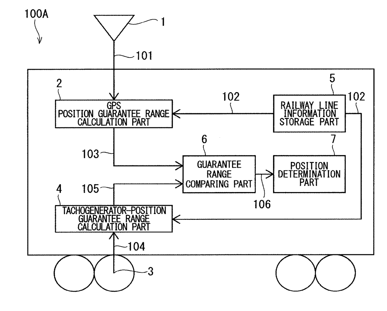
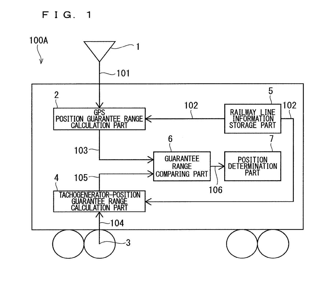
[0031]FIG. 1 is a diagram illustrating a configuration of a train position detecting device 100A according to the first embodiment. In the drawings, identical or corresponding components are denoted by the same reference numerals, and this is to be common to the entire text of the description. In addition, forms of components that appear in the description are merely illustrative, and are not intended to be limited to the description.
[0032]In FIG. 1, the train position detecting device 100A is provided with a GPS antenna 1, a GPS position guarantee range calculation part 2, a tachometer generator 3, a tachogenerator-position guarantee range calculation part 4...
second embodiment
B. Second Embodiment
[0059]In a second embodiment of the present invention, processing for shortening a margin distance with respect to the front end position of the own train will be described. The processing enables to appropriately shorten a train interval with respect to a preceding train, and to enter a forward speed limit zone at an appropriate speed.
B-1. Configuration
[0060]A configuration of a train position detecting device according to the second embodiment is similar to that of the train position detecting device 100A in FIG. 1.
B-2. Operation
[0061]FIG. 5 is a flowchart illustrating an operation of the train position detecting device according to the second embodiment. The operation of the train position detecting device according to the second embodiment will be described below with reference to FIGS. 1 and 5.
[0062]The GPS position guarantee range calculation part 2 calculates the GPS position guarantee range 103 in a manner similar to the first embodiment. Moreover, the GP...
third embodiment
C. Third Embodiment
[0076]In a third embodiment of the present invention, in addition to the processing in the first embodiment, positioning results in the past are further referred to, thereby performing processing to further shorten a margin distance.
C-1. Configuration
[0077]FIG. 8 is a diagram illustrating a configuration of a train position detecting device 100B according to the third embodiment. A configuration of the train position detecting device 100B is similar to that of the train position detecting device 100A according to the first embodiment except that an estimated train rear end position 107 is output from the position determination part 7 to the guarantee range comparing part 6.
C-2. Operation
[0078]Terms related to the rear-end-position guarantee range will be described with reference to FIG. 9. The tachogenerator rear-end-position guarantee range + is a front end value of the tachogenerator rear-end-position guarantee range in the train forward traveling direction, and...
PUM
 Abstract
Description
Claims
Application Information
 - R&D
- Intellectual Property
- Life Sciences
- Materials
- Tech Scout
- Unparalleled Data Quality
- Higher Quality Content
- 60% Fewer Hallucinations
Browse by: Latest US Patents, China's latest patents, Technical Efficacy Thesaurus, Application Domain, Technology Topic, Popular Technical Reports.
© 2025 PatSnap. All rights reserved.Legal|Privacy policy|Modern Slavery Act Transparency Statement|Sitemap|About US| Contact US: help@patsnap.com