Steering system
- Summary
- Abstract
- Description
- Claims
- Application Information
AI Technical Summary
Benefits of technology
Problems solved by technology
Method used
Image

Examples
first embodiment
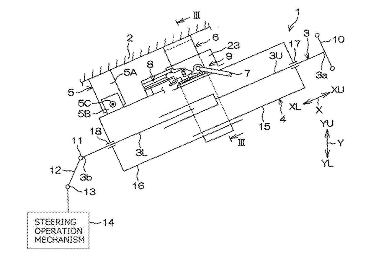
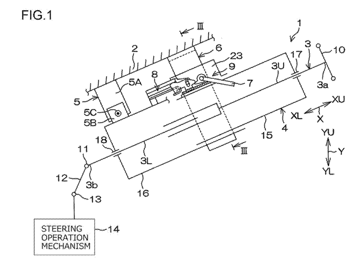
[0029]The following describes embodiments embodying the present invention according to the drawings. FIG. 1 is a schematic side view of a steering system 1 according to the present invention. The left side of FIG. 1 corresponds to the front side of a vehicle body 2 where the steering system 1 is mounted, and the right side of FIG. 1 corresponds to the rear side of the vehicle body 2. The upper side of FIG. 1 corresponds to the upper side of the vehicle body 2, and the lower side of FIG. 1 corresponds to the lower side of the vehicle body 2. FIG. 2 is a perspective view of the steering system 1.
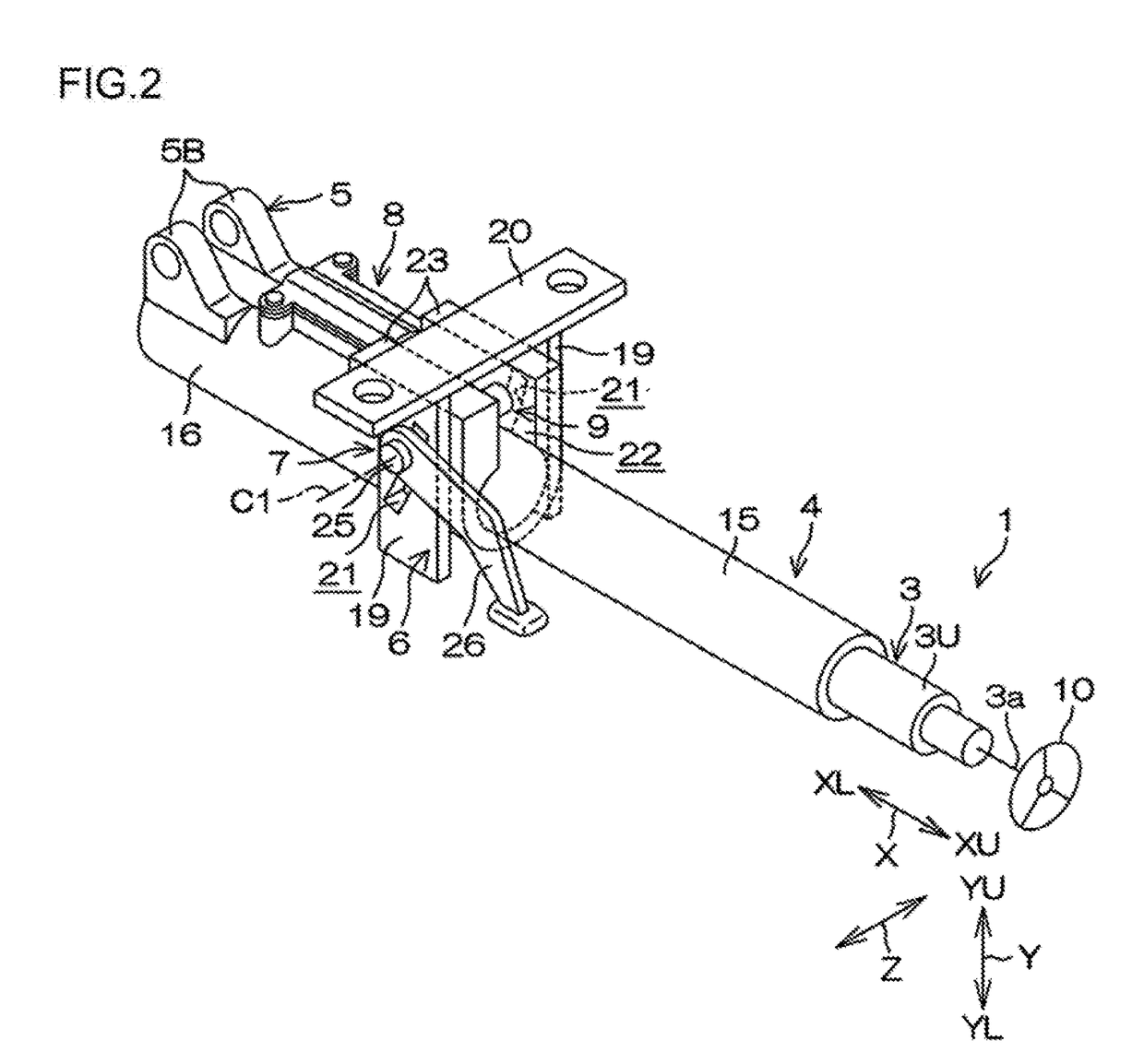
[0030]With reference to FIG. 1, the steering system 1 mainly includes a steering shaft 3, a column jacket 4, a lower bracket 5, an upper bracket 6, a fastening mechanism 7, an impact absorbing mechanism 8, and a tooth lock mechanism 9. The extending direction of the steering shaft 3 corresponds to a column axial direction X. A steering member 10, such as a steering wheel, is connected to one e...
second embodiment
[0112]Consequently, during the secondary collision, the guide shaft 81 is fractured at a stable fracture load by application of a load from the pair of support portions 160 that is not affected by variation in displacement of the pair of fastened portions 23. This enables obtaining of stable impact absorbing characteristics during the secondary collision. The pair of support portions 160 include the pair of slide guide surfaces 161 that slidingly guide the pair of side surfaces 73c on the body portion 73 of the second tooth member 70. During the secondary collision, the slide guide surfaces 161 on the pair of support portions 160 restrict the second tooth member 70 from moving in the axial direction of the guide shaft 81, and consequently, the guide shaft 81 is fractured by a more stable fracture load during the secondary collision. This enables obtaining of the stable impact absorbing characteristics during the secondary collision. FIGS. 17A and 17B are sectional views of a structu...
sixth embodiment
[0126]FIGS. 20A and 20B are schematic side views of a tooth lock structure in a steering system according to the present invention. FIG. 20A showing the meshed state (locked state), and FIG. 20B showing the unmeshed state (unlocked state).
[0127]As shown in FIGS. 20A and 20B, a second tooth member 70Q includes a singular second tooth 74, the engagement projection 77, and an insertion hole 82Q formed by, for example, a circular hole. An insertion shaft 81Q supported by the lower jacket via a supporting mechanism is inserted in the insertion hole 82Q. The second tooth member 70Q is supported so as to be rotatable about the insertion shaft 81Q. The second tooth member 70Q is displaced between the meshed state and the unmeshed state along with the rotation about the insertion shaft 81Q. The insertion shaft 81Q is formed of a resin, and is fractured during the secondary collision.
[0128]An inner surface 82Qa of the insertion hole 82Q has formed thereon a projection 800 serving as a fractur...
PUM
 Abstract
Description
Claims
Application Information
 - R&D Engineer
- R&D Manager
- IP Professional
- Industry Leading Data Capabilities
- Powerful AI technology
- Patent DNA Extraction
Browse by: Latest US Patents, China's latest patents, Technical Efficacy Thesaurus, Application Domain, Technology Topic.
© 2024 PatSnap. All rights reserved.Legal|Privacy policy|Modern Slavery Act Transparency Statement|Sitemap