Plug for connection to a socket of an electronic equipment box panel, having means of self-alignment

a technology of electronic equipment box and socket, which is applied in the direction of coupling device connection, optical element, instruments, etc., can solve the problems of long dedicated installation time, obvious cost and restrictive solutions, and troublesome alignment of contacts supported by plugs b>1/b> and those supported by electronic components b>82/b>, so as to prevent any pivoting of the lever and avoid accidental pivoting of the locking lever

Active Publication Date: 2018-01-11
RADIALL SA
View PDF10 Cites 18 Cited by
  • Summary
  • Abstract
  • Description
  • Claims
  • Application Information

AI Technical Summary

Benefits of technology

[0042]The blocking tongue according to the invention makes it possible to avoid accidental pivoting of the locking lever which is liable to cause unwanted unlocking of the plug from the socket. In fact, the tongue may slide in a groove provided for this purpose on the locking lever, between a position advanced towards the front portion of the plug body and a position retracted from the latter. One may associate this with a mechanical latching effect of the tongue to hold it in its advanced or retracted position.
[0043]When the user wishes to block the lever in its locking position, he then moves the tongue into its retracted position, which causes it to be inserted beneath the rim of the packing gland nut, thereby preventing any pivoting of the lever.

Problems solved by technology

In this configuration, the alignment of the contacts supported by the plug 1 and those supported by the electronic component 82 is problematical.
This solution is obviously costly and restrictive.
Furthermore, the dedicated installation time may be long when the electronic equipment needs to implement a multitude of connectors, and thus of sockets needing to be attached and centred.
Moreover, the position in z is not necessarily corrected, which means relying on the dimensional reference chains to ensure the relative positioning between the electronic component and the plug contact(s).

Method used


Image

  • Plug for connection to a socket of an electronic equipment box panel, having means of self-alignment
  • Plug for connection to a socket of an electronic equipment box panel, having means of self-alignment
  • Plug for connection to a socket of an electronic equipment box panel, having means of self-alignment

Examples


Embodiment Construction

[0070]Other advantages and features of the invention will better emerge from a perusal of the detailed description of exemplary embodiments of the invention given as an illustration and not a limitation, making reference to the following figures, where:

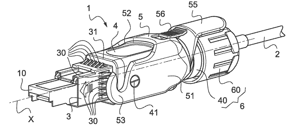
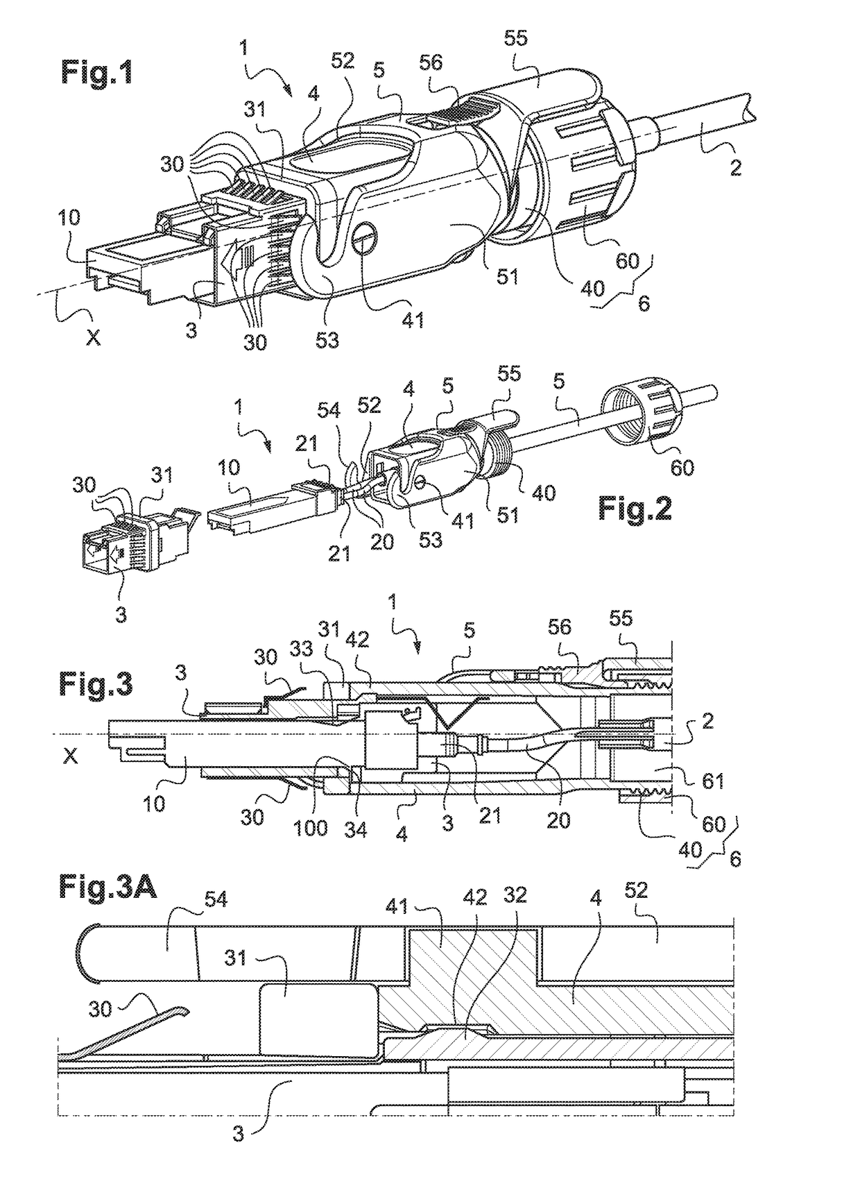
[0071]FIG. 1 is a perspective view of a first example of the plug according to the invention, the plug comprising an optoelectronic converter of “transceiver SFP” type, projecting to the front of the plug;

[0072]FIG. 2 is an exploded view of the plug according to FIG. 1;

[0073]FIG. 3 is a partial longitudinal section view of the plug according to FIGS. 1 and 2;

[0074]FIG. 3A is a detailed top view of the plug according to one of FIGS. 1 to 3 showing the floating mount of the rear portion of the plug body around its front portion;

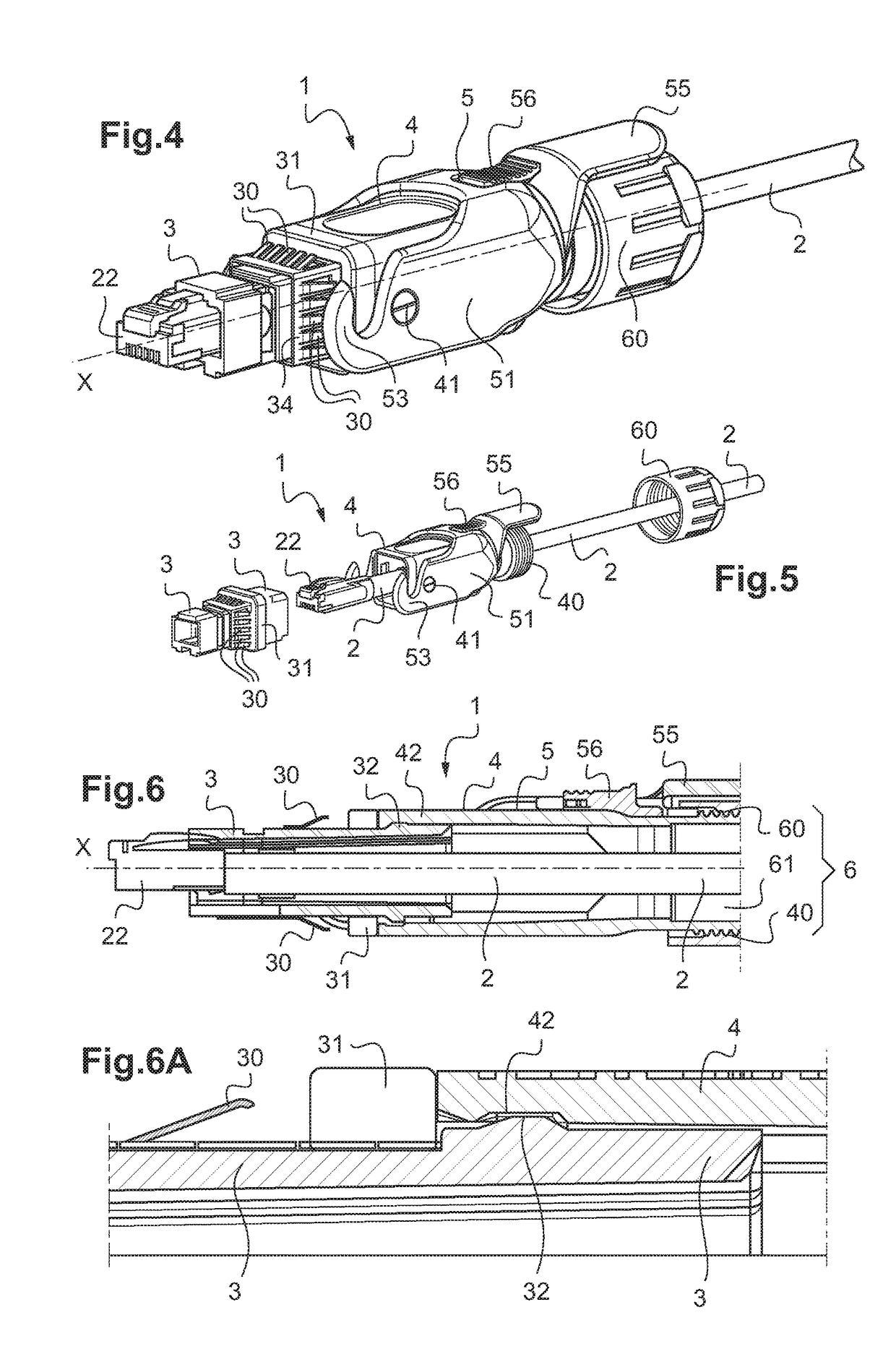
[0075]FIG. 4 is a perspective view of a second example of the plug according to the invention, the plug comprising a connector of type RJ45, projecting to the front of the plug;

[0076]FIG. 5 is an exploded view of...


PUM


Abstract

The present invention concerns a plug intended to be mounted on at least one cable whose one end supports one or more contacts comprising:
    • a body, comprising:
      • a front portion extending along a longitudinal axis, the front portion being designed to be lodged in a socket, the front portion being adapted to lodge and hold the contact(s) or at least an optoelectronic converter connected to the contact(s);
      • a rear portion forming a sheath, designed to lodge the end of the cable, itself supporting the contact(s); the rear portion being mounted floating about the front portion;
    • a plurality of flexible tabs made of electrically conductive material, distributed on the outer periphery of the front portion, the flexible tabs being adapted to remain in mechanical contact with the interior of the socket when the front portion is lodged in the latter.

Description

TECHNICAL FIELD[0001]The present invention concerns a plug including a cordless key for emission by wireless network, of the wife or Bluetooth® type, or a plug intended to be mounted on at least one cable supporting one or more contacts, and to be connected to a socket of an electronic equipment box panel.[0002]These contacts may be of type RJ45, for power, data, a combination of the two, or optical. These contacts in particular may be an optoelectronic converter interface of type SFP / SFP+, or optical contacts.[0003]The invention applies in particular to plugs for connection to sockets of electronic equipment implementing a plurality of optical and / or electrical channels with connections which are found in an outdoor environment and / or in harsh conditions, especially in telecommunications installations such as mobile telephony relay antennas, in high-speed data transmission networks for home or industry, in surveillance camera networks or for data transmission in railway installatio...

Claims


Application Information

Patent Timeline
Patent Type & Authority Applications(United States)
IPC IPC(8): H01R13/631H01R13/629G02B6/42H01R13/53H01R43/26H01R13/639
CPCH01R13/6315H01R13/62933H01R13/53G02B6/4278H01R13/639H01R43/26G02B6/4284H01R13/506H01R13/516H01R13/6582H01R12/91
Inventor DUPEUX, BENOITBOURGEAS, FABIENLOMUSCIO, DOMINIQUE
Owner RADIALL SA
Why Eureka
Try Eureka