Interpolator

a technology of interpolator and interpolation, which is applied in the field of interpolator, can solve the problems of non-linearity and high sensitivity to process variations of conventional interpolators, and achieve the effects of improving the sensitivity of process variations and reducing the difficulty of interpolation

Active Publication Date: 2018-01-11
VIA ALLIANCE SEMICON CO LTD
View PDF1 Cites 2 Cited by
  • Summary
  • Abstract
  • Description
  • Claims
  • Application Information

AI Technical Summary

Benefits of technology

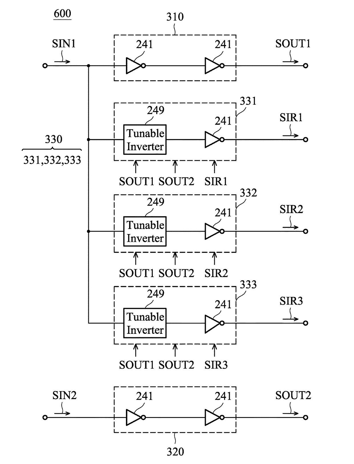
[0019]In some embodiments, the tunable delay circuit is a digital control circuit which includes: a delay chain, delaying the first output signal for different delay times, so as to generate a plurality of delay signals; a multiplexer, selecting one of the delay signals as the output interpolation signal according to a number; a counter, incrementing the number according to a control clock; and a decision circuit, generating the control clock according to the first output signal, the second output signal, and the output interpolation signal.
[0020]In some embodiments, the decision circuit includes: a first P-type transistor, wherein the first P-type transistor has a control terminal coupled to a first node, a first terminal coupled to a supply voltage, and a second terminal coupled to the first node; a current sink, drawing a first current from the first node; a second P-type transistor, wherein the second P-type transistor has a control terminal coupled to the first node, a first terminal coupled to the supply voltage, and a second terminal coupled to a second node; a first NAND gate, wherein the first NAND gate has a first input terminal for receiving the first output signal, a second input terminal for receiving an inverse of the output interpolation signal, and an output terminal for outputting a first tuning signal at a third node; a third P-type transistor, wherein the third P-type transistor has a control terminal coupled to the third node, a first terminal coupled to the second node, and a second terminal coupled to a first control node; a first N-type transistor, wherein the first N-type transistor has a control terminal coupled to a fourth node, a first terminal coupled to a ground voltage, and a second terminal coupled to the fourth node; a current source, supplying a second current to the fourth node; a second N-type transistor, wherein the second N-type transistor has a control terminal coupled to the fourth node, a first terminal coupled to the ground voltage, and a second terminal coupled to a fifth node; a first AND gate, wherein the first AND gate has a first input terminal for receiving the output interpolation signal, a second input terminal for receiving an inverse of the second output signal, and an output terminal for outputting a second tuning signal at a sixth node; a third N-type transistor, wherein the third N-type transistor has a control terminal coupled to the sixth node, a first terminal coupled to the fifth node, and a second terminal coupled to the first control node; and a capacitor, coupled between the first control node and the ground voltage, wherein the control clock is generated according to a control voltage at the first control node.
[0021]In some embodiments, the decision circuit further includes: a second switch element, coupled between the first control node and a reference voltage, wherein the second switch element is selectively closed or opened according to an inverse of the first output signal, and wherein the reference voltage is substantially a half of the supply voltage; a comparator, wherein the comparator has a positive input terminal coupled to the reference voltage, a negative input terminal coupled to the first control node, and an output terminal coupled to a seventh node; a third switch element, coupled between the seventh node and a second control node, wherein the third switch element is selectively closed or opened according to a first switching signal, and wherein the second control node is arranged for outputting the control clock; and a fourth switch element, coupled between the ground voltage and the second control node, wherein the fourth switch element is selectively closed or opened according to a second switching signal, wherein the first switching signal and the second switching signal are generated according to the first output signal and the second output signal.

Problems solved by technology

However, conventional interpolators often have the problem of non-linearity and high sensitivity to process variations.

Method used


Image

  • Interpolator
  • Interpolator
  • Interpolator

Examples


Embodiment Construction

[0036]In order to illustrate the purposes, features and advantages of the invention, the embodiments and figures of the invention are described in detail as follows.

[0037]Certain terms are used throughout the description and following claims to refer to particular components. As one skilled in the art will appreciate, manufacturers may refer to a component by different names. This document does not intend to distinguish between components that differ in name but not function. In the following description and in the claims, the terms “include” and “comprise” are used in an open-ended fashion, and thus should be interpreted to mean “include, but not limited to . . . ”. The term “substantially” means the value is within an acceptable error range. One skilled in the art can solve the technical problem within a predetermined error range and achieve the proposed technical performance. Also, the term “couple” is intended to mean either an indirect or direct electrical connection. According...


PUM


Abstract

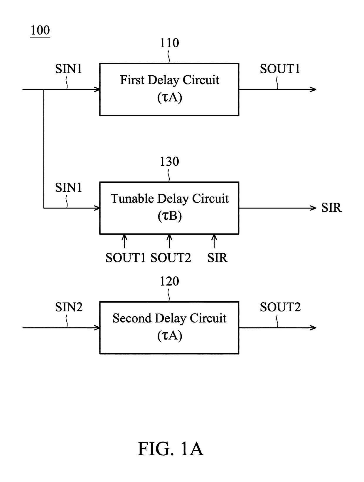
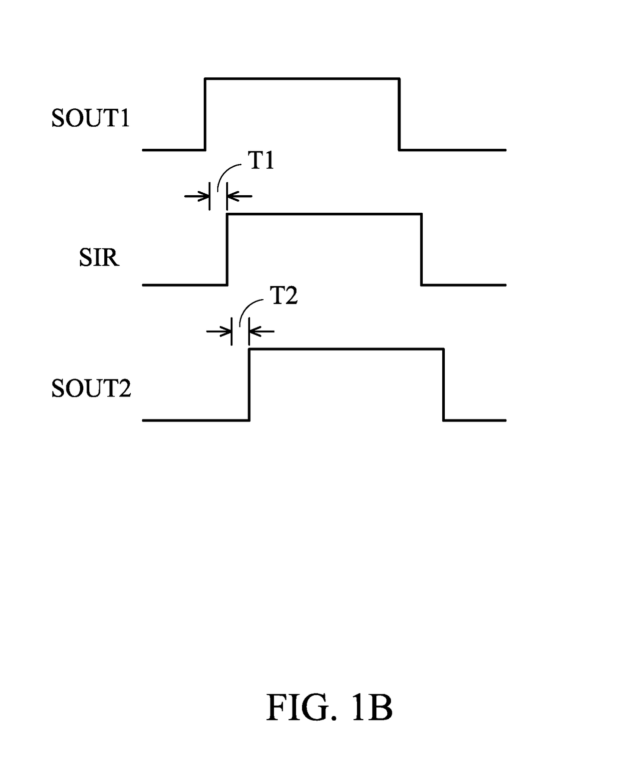
An interpolator includes a first delay circuit, a second delay circuit, and a tunable delay circuit. The first delay circuit delays a first input signal for a fixed delay time, so as generate a first output signal. The second delay circuit delays a second input signal for the fixed delay time, so as to generate a second output signal. The tunable delay circuit delays the first input signal for a tunable delay time, so as to generate an output interpolation signal. The tunable delay time is determined according to the first output signal, the second output signal, and the output interpolation signal.

Description

CROSS REFERENCE TO RELATED APPLICATIONS[0001]This application is a Continuation-In-Part of application Ser. No. 15 / 203,392, filed Jul. 6, 2016, the entirety of which is incorporated by reference herein. Also, this application is a Continuation-In-Part of application Ser. No. 15 / 243,287, filed Aug. 22, 2016, the entirety of which is incorporated by reference herein.BACKGROUND OF THE INVENTIONField of the Invention[0002]The disclosure generally relates to an interpolator, and more specifically, to a highly-accurate phase interpolator.Description of the Related Art[0003]In the field of electric circuits, interpolators are common and used in many applications to generate multi-phase signals. For example, a phase interpolator is a critical circuit in the receiver of a serial link, and it allows the receiver to adjust the phase of its sampling clocks. However, conventional interpolators often have the problem of non-linearity and high sensitivity to process variations. Accordingly, there ...

Claims


Application Information

Patent Timeline
Patent Type & Authority Applications(United States)
IPC IPC(8): H03K5/134H03K17/687H03K19/20H03K5/00
CPCH03K5/134H03K19/20H03K2005/00052H03K2005/00078H03K17/6872H03D13/003H03K2005/00039H03L7/085H03L7/087H03L7/0998H04L7/033
Inventor LEE, YEONG-SHENG
Owner VIA ALLIANCE SEMICON CO LTD
Why Eureka
Try Eureka