

Receiver for receiving data in a broadcast system using redundancy data
- Summary
- Abstract
- Description
- Claims
- Application Information
AI Technical Summary
Benefits of technology
Problems solved by technology
Method used
Image

Examples
embodiment 10
11. The receiver as defined in embodiment 10,
wherein said selection unit is configured to select a redundancy data source based on a redundancy data source address list indicating the addresses of the at least two redundancy data sources and to subscribe to a selected redundancy data source by forwarding an identification of the receiver to the selected redundancy data source.
11a. The receiver as defined in one of the preceding embodiments,
wherein it is configured to access a multicast redundancy data stream if it experiences round trip delays below a predetermined threshold and to use a peer-to-peer access of redundancy data if it experiences round trip delays above said predetermined threshold.
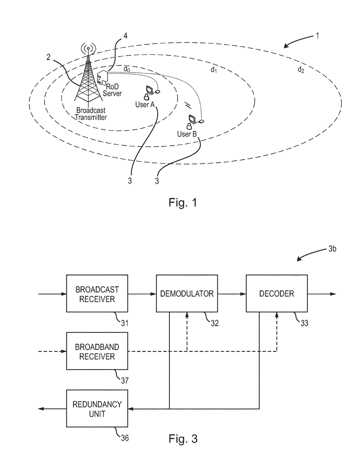
12. A broadband server for providing redundancy data to a receiver of a broadcast system via a broadband system, comprising:
[0216]a data receiving unit configured to receive data from a broadcast transmitter of said broadcast system,
[0217]a data conversion unit configured to convert the rece...
embodiment 12
13. The broadband server as defined in embodiment 12,
wherein said data receiving unit is configured to receive data that have been or will be broadcasted by the broadcast transmitter and wherein said data conversion unit is configured to generate the at least two redundancy data streams from said data.
14. The broadband server as defined in one of the preceding embodiments 12 to 13, further comprising a signalling unit configured to signal a redundancy data source address list for use by a receiver to select a redundancy data source and to subscribe to a selected redundancy data source, said redundancy data source address list indicating the addresses of the at least two redundancy data sources.
15. The broadband server as defined in one of the preceding embodiments 12 to 14,
wherein said at least two redundancy data sources comprise at least two multicast redundancy servers.
embodiment 15
16. The broadband server as defined in embodiment 15,
wherein each of said at least two multicast redundancy servers is configured to multicast its redundancy data stream receivers that have selected said redundancy data stream.
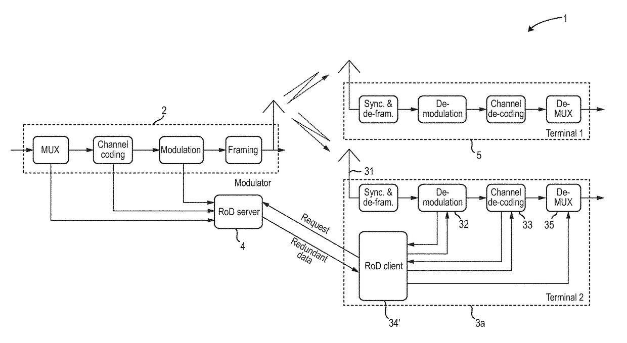
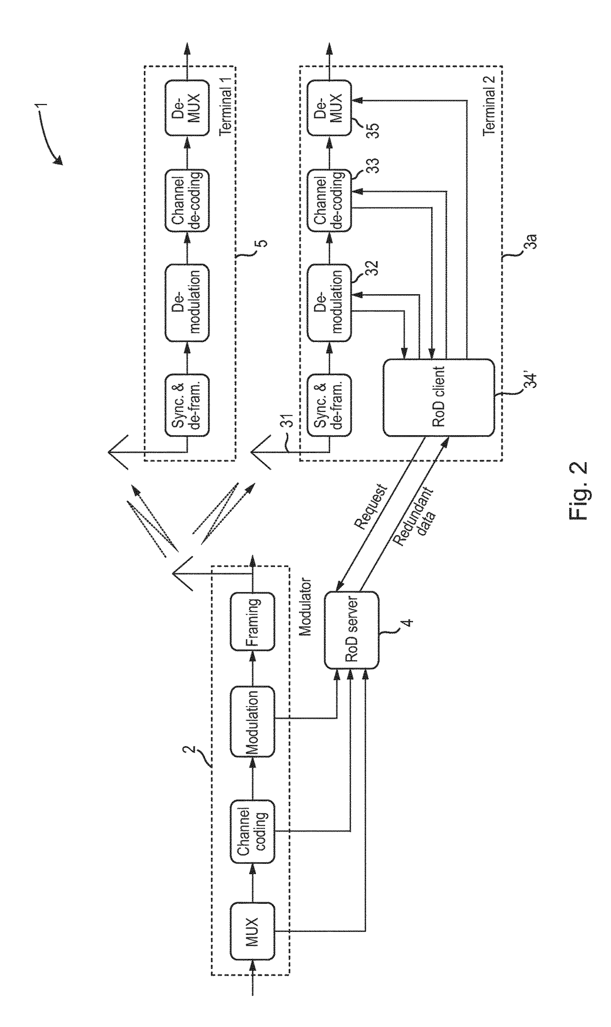
17. A receiving method for receiving data, comprising:
[0219]receiving, via a broadcast system, a receiver input data stream comprising a plurality of channel symbols represented by constellation points in a constellation diagram,
[0220]demodulating said channel symbols into codewords,
[0221]a decoding said codewords into output data words,
[0222]selecting or requesting via a broadband system, if demodulation of a channel symbol and / or decoding of a codeword is erroneous or likely to fail, redundancy data for demodulation of future channel symbols and / or decoding of future codewords,
[0223]obtaining said redundancy data via said broadband system,
wherein said demodulating and / or said decoding is configured to use the obtained redundancy data to demodulate the respec...
PUM
 Abstract
Description
Claims
Application Information