Apparatus and method of screen decorating metallic containers

Inactive Publication Date: 2018-01-18
BALL CORP
View PDF0 Cites 1 Cited by
  • Summary
  • Abstract
  • Description
  • Claims
  • Application Information

AI Technical Summary

Benefits of technology

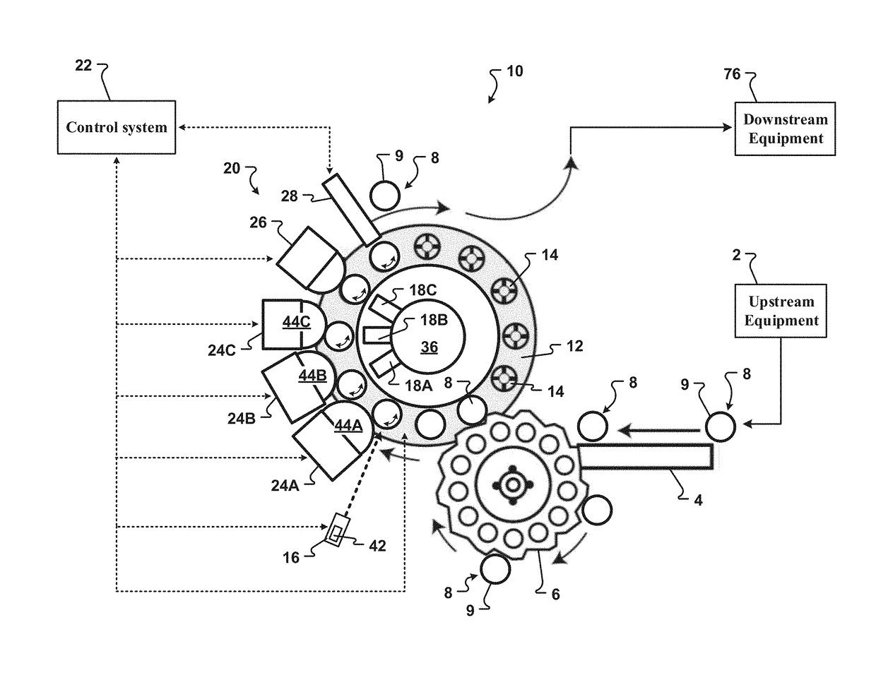
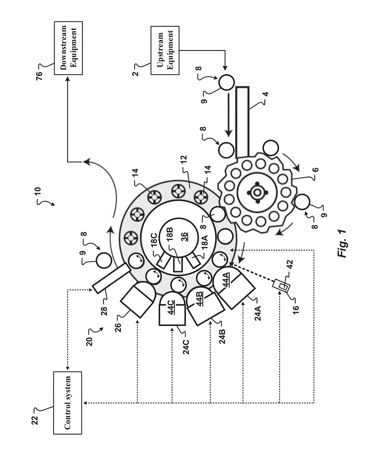
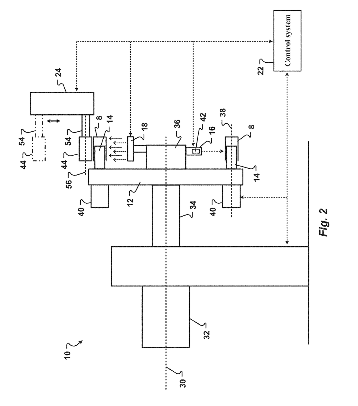
The present invention is about a machine and method for decorating metallic containers quickly and efficiently. The machine uses a screen print unit to apply decorations to the exterior surface of the container. It can transfer a variety of materials like ink, varnish, or adhesive. Additionally, the machine can apply additional decorations without interfering with the previously applied ones. Furthermore, the machine has a control system that can detect the orientation of the container and adjust the mandrel to ensure correct placement of the decoration. Overall, the machine allows for higher quality decorations and is cost-effective and reliable for metallic container decoration.

Problems solved by technology

For example, the metallic body prevents CO2 migration and transmission of UV radiation which may damage the contents of the metallic container, negatively influencing the effectiveness of ingredients, as well as the flavor, appearance, or color of the product.
Because of the high speeds of the production lines, techniques or processes that may work in other industries or with containers formed of other materials do not necessarily work at the high speeds required for metallic container production lines.
However, prior art off-set decorators do not provide a sufficient weight or thickness of ink to achieve some desired decorations.
Other prior art decorators cannot transfer some specialty inks or pigmented inks.
Further, some prior art decorators which include rollers cannot register decorations with previously applied decorations.
The flat screens of these apparatus result in relatively slow production rates that are not suitable for high-speed decorators required in the commercial container industry.
Known screen printing assemblies within prior art silk screen apparatus also frequently occupy a substantial amount of space.
As a result, the space provided for curing the screen-printed ink is often inadequate.
Thus, prior art silk screen apparatus are generally undesirable for multi-colored screen printing operations where curing is required between each screen printing workstation.
The limited space of the prior art silk screen apparatus is more significant when screen printing multiple registered layers of a printing ink.
This arrangement of the mandrels detrimentally increases the size of the silk screen apparatus such that the silk screen apparatus takes up a substantial, and unacceptable, amount of space in the production facility.
Further, prior art silk screen apparatuses do not register the additional decorations with previous decorations of the metallic containers.
For example, prior art silk screen printing apparatuses cannot register a decoration with a previous decoration applied by an upstream printer.
Thus, prior art silk screen apparatuses cannot typically be used with previously decorated metallic containers.
However, these rollers cannot be registered with previously applied decorations.
Accordingly, the prior art varnisher cannot selectively apply varnish to only selected portions of the container exterior surface.
Thus, the prior art varnisher may not be used to form a metallic container with a combination of varnished and unvarnished decorations.
Further, prior art varnishers cannot apply two different varnishes to different portions of the metallic container.
Other prior art varnishers cannot leave one cylindrical exterior portion of a metallic container unvarnished while varnishing a second cylindrical exterior portion of the metallic container.
However, the Anilox roller is not capable of applying sufficient amounts of specialty inks or varnishes to the printing plate to produce certain desired decorations on metallic containers.
Due to the limitations associated with prior art apparatus and methods of decorating metallic containers, there is an unmet need for a decorator that applies decorations to metallic containers without sacrificing production efficiency or image quality and detail and that is operable to register the decorations with previously formed decorations or other indicia on the exterior surface of a cylindrical container.

Method used


Image

  • Apparatus and method of screen decorating metallic containers
  • Apparatus and method of screen decorating metallic containers
  • Apparatus and method of screen decorating metallic containers

Examples


Embodiment Construction

[0172]The present invention has significant benefits across a broad spectrum of endeavors. It is the Applicant's intent that this specification and the claims appended hereto be accorded a breadth in keeping with the scope and spirit of the invention being disclosed despite what might appear to be limiting language imposed by the requirements of referring to the specific examples disclosed. To acquaint persons skilled in the pertinent arts most closely related to the present invention, a preferred embodiment that illustrates the best mode now contemplated for putting the invention into practice is described herein by, and with reference to, the annexed drawings that form a part of the specification. The exemplary embodiment is described in detail without attempting to describe all of the various forms and modifications in which the invention might be embodied. As such, the embodiments described herein are illustrative, and as will become apparent to those skilled in the arts, may be...


PUM


Abstract

An apparatus and methods of decorating a metallic container are provided. More specifically, the present invention relates to apparatus and methods used to provide a decoration on a predetermined surface of a metallic container body. The decoration may be registered with decorations previously applied to the container body. In one embodiment, the apparatus includes a screen print unit with a cylindrical body. The cylindrical body rotationally applies a predetermined type or color of ink or other coating, such as a varnish, to the cylindrical body. In one embodiment, the apparatus applies a varnish to a selected portion of the cylindrical body without applying the varnish to all of the cylindrical body. Additionally, the apparatus may also include a foiling unit that applies a label to the cylindrical body.

Description

CROSS-REFERENCE TO RELATED APPLICATIONS[0001]This application claims priority under 35 U.S.C. §119(e) to U.S. Provisional Patent Application Ser. No. 62 / 361,630, filed Jul. 13, 2016, entitled “Apparatus and Method of Decorating Metallic Containers,” and which is incorporated herein in its entirety by reference.FIELD OF THE INVENTION[0002]The present invention relates generally to the manufacture of containers. More specifically, this invention provides an apparatus and methods used to decorate metallic containers. In one embodiment, a screen print unit can apply a decorating material to a predetermined portion of an exterior surface of a metallic container. The decorating material may be registered with a decoration previously applied to the container exterior surface. The decorating material may be one of an ink, a varnish, and an adhesive.BACKGROUND[0003]Metallic containers offer distributors and consumers many benefits. The metallic body of a metallic container provides optimal p...

Claims


Application Information

Patent Timeline
IPC IPC(8): B05C11/02B05D5/06B05D3/12B05D1/40B05B13/00B44D2/00
CPCB05C11/023B05D3/12B44D2/00B05D1/40B05B13/00B05D5/061B41M1/12B41M1/28B41M1/40B41F15/00B41F15/06B41F15/0872B41F17/14B41F17/22B41J3/40733
Inventor NICOL, PAULGALLEY, JASON
Owner BALL CORP
Why Eureka
Try Eureka