
System and method for monitoring and adjusting a decorator for containers

a technology for decorators and containers, applied in the field of decorators, can solve the problems of not working at the high speed required for metallic container production lines, affecting the flavor, appearance or color of containers, and requiring considerable labor and associated expense, and achieves the effects of cost-effectiveness, fast and reliabl

Active Publication Date: 2021-06-15
BALL CORP
View PDF477 Cites 0 Cited by
  • Summary
  • Abstract
  • Description
  • Claims
  • Application Information

AI Technical Summary

Benefits of technology

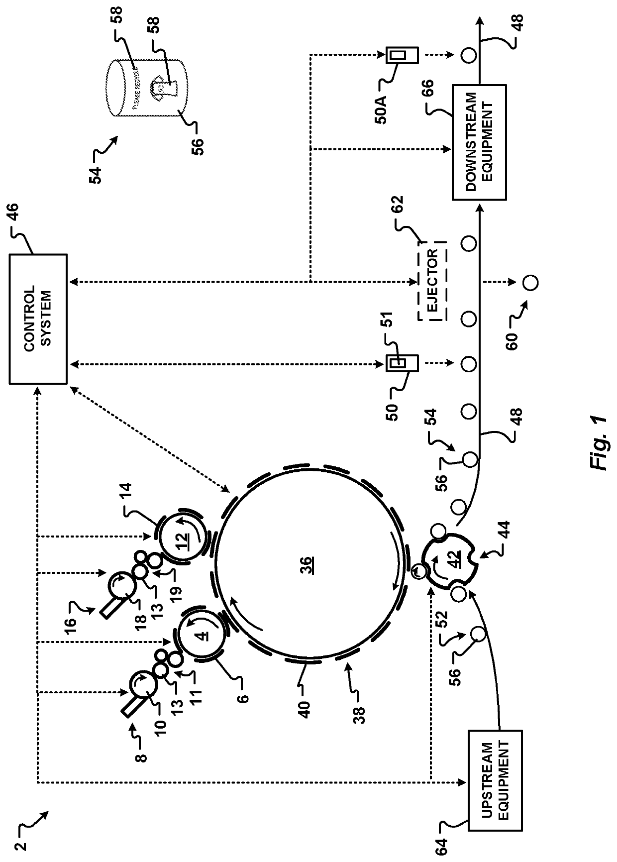
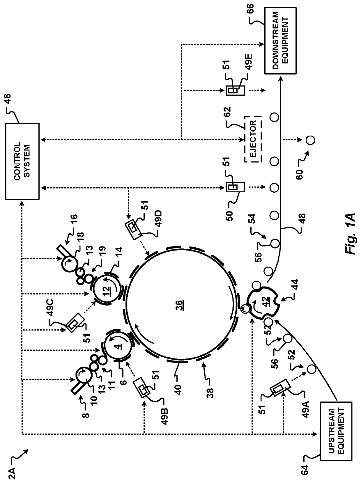
[0019]The present invention provides various apparatus, instructions stored in a non-transitory computer readable medium, and methods for decorating metallic containers in a cost-effective, fast, and reliable manner. One aspect of the present invention is a closed-loop decorator assembly and system that includes a control system that can detect a deficient decoration on a cylindrical shaped metallic container. When the control system detects a deficient decoration, the control system can determine the cause of the deficiency. The control system may then automatically correct the deficiency. Additionally, or alternatively, the control system can alert an operator that specific adjustments are required. If the cause of the deficiency can be corrected by adjusting the amount of ink transferred to the metallic container, in one embodiment the control system can send a signal to adjust at least one ink blade to correct the deficient decoration on subsequent metallic containers. Further, a signal can be sent to the equipment on the production line to reject any container which has a flawed decoration. Flawed decorations can include, but are not limited to, color variations, ink density, ink thickness, ink color, incorrect positions of indicia, and quality of the decoration. In one embodiment, when the deficiency cannot be corrected by the control system, the control system can automatically stop the production line.
[0038]Yet another aspect of the present invention is a control system for a decorator that is capable of determining an acceptable decoration of a metallic container and whether the decoration quality falls within predetermined quality standards. Once the control system establishes an acceptable decoration, the control system can detect a decoration that varies from the acceptable decoration. In this manner, the control system can determine that a metallic container includes an unacceptable, or deficient, decoration.
[0047]In another embodiment, the signal causes at least one of the inking assembly, the ink roller, the plate cylinder, and the blanket cylinder to move in a specific direction. In yet another embodiment, the control system can send a signal to an actuator to alter a position of at least one of a printing plate on the plate cylinder and a transfer blanket on the blanket cylinder. In another embodiment, the control system can send a signal to an actuator of a ductor roller associated with an inking assembly. The signal can alter a rate of movement of the ductor roller. In this manner, the control system can adjust the amount of ink transferred to a printing plate associated with the inking assembly. More specifically, the control system can send a signal to decrease or increase the rate of movement of the ductor roller. Optionally, in one embodiment, the method further comprises sending, by the control system, a signal to an ejector to remove the container with the abnormal decoration from the conveyor associated with the decorator.
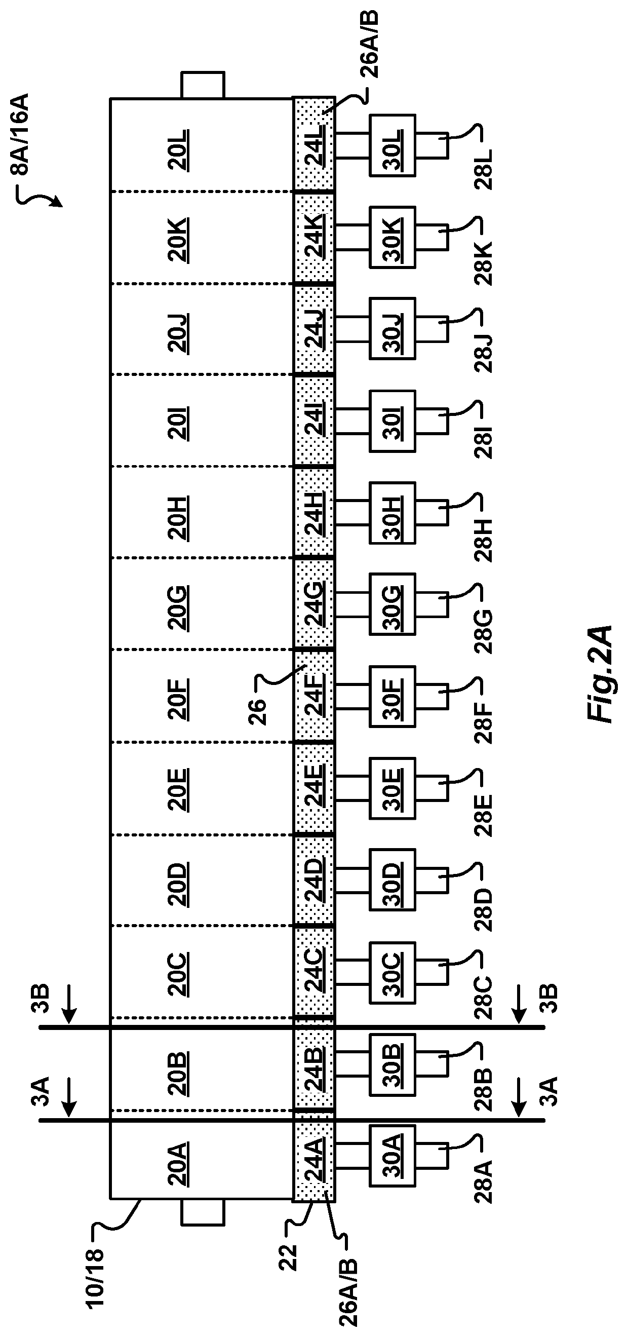
[0053]In one embodiment, the instructions further include and instruction to send a signal to an actuator to adjust an ink blade. In one embodiment, the signal causes the actuator to move the ink blade in a specified direction with respect to an ink roller of the decorator to alter an amount of ink applied to a portion of the ink roller. In another embodiment, the signal causes the actuator to move at least one ink blade of the decorator to a position which either increases or decreases the amount of ink transferred to a portion of the ink roller.
[0061]In one embodiment, the signal causes at least one of an inking assembly, an ink roller, a ductor roller, a plate cylinder, a printing plate on the plate cylinder, a blanket cylinder, and a transfer blanket of the decorator to move in a specific direction. In another embodiment, the signal causes an actuator to move an ink blade of the decorator to a position which either increases or decreases the amount of ink transferred to a portion of an ink roller. In still another embodiment, the signal causes an actuator associated with one or more of an inking assembly, an ink roller, a ductor roller, a plate cylinder, a printing plate on the plate cylinder, a blanket cylinder, and a transfer blanket of the decorator to move in the specific direction. Optionally, the signal can alter a rate or timing of movement of a ductor roller. In this manner, the amount of ink transferred to a printing plate can be altered.
[0065]It is another aspect of the present invention to provide a decorator with a ductor roller that can be adjusted while the decorator is in operator decorating metallic containers. An actuator is associated with the ductor roller. The actuator is operable to alter a rate of movement of the ductor roller. In this manner an amount of ink transferred from an inking assembly to a printing plate can be altered. In one embodiment, the actuator can alter one or more of the timing of the movement of the ductor roller. In another embodiment, the actuator is operable to receive a signal from a control system.

Problems solved by technology

For example, the metallic body prevents CO2 migration and transmission of UV radiation which may damage beverages, negatively influencing the flavor, appearance, or color of the product.
Further, some consumers avoid plastic containers due to concerns that the plastic may leach chemicals into consumable products.
Because of the high speeds of container production lines, techniques or processes that may work in other industries or with containers formed of other materials do not necessarily work at the high speeds required for metallic container production lines.
Producing acceptable decorations on metallic containers with prior art decorators is dependent upon the skill and attentiveness of the operator and requires considerable labor and associated expense.
More specifically, for each production run to decorate metallic containers with a decoration using a prior art decorator, the ink keys of each inking assembly are set to an initial position which takes a significant amount of time.
Considering the high production speeds at which metallic container production lines typically operate, this is a considerable amount of down time and lost productivity.
When this occurs, the decoration transferred to the metallic container may be deficient because one or more of the color, density, depth, alignment, and consistency of the decoration do not meet targets set by a customer.
Accordingly, the decorator must be taken out of production to adjust the position of the ink keys resulting in further down time and lost productivity.
Determining which ink keys to adjust to correct the deficiency can be difficult if the deficient decoration includes inks from two or more different inking assemblies.
Additionally, the ink roller, printing plates, and printing blankets may become worn and require adjustment or replacement during a production run.
Manually identifying a deficient decoration and then manually adjusting the decorator takes a significant amount of time.
Due to the high speeds of beverage container production lines, several hundred or even several thousand metallic containers with deficient decorations may be produced before the operator identifies the problem and then properly adjusts the ink keys.
Accordingly, a large amount of waste metallic containers with deficient decorations are often created by prior art decorators.
This wastes valuable production time and may delay the operation of downstream production equipment due to a lack of decorated metallic containers.
Adjusting ink keys of prior art decorators is difficult and can be dangerous.
Some ink keys are difficult to access.
Tools used to adjust the ink keys can unintentionally damage the decorator.
Further, tools used by the operator may be inadvertently misplaced or left within the decorator assembly, requiring additional downtime and the associated cost of loss of production.
Additionally, the operator may be injured while reaching into the decorator to adjust the ink keys.
Due to the limitations associated with existing methods and apparatus used to decorate metallic containers, there is an unmet need for an apparatus and method of automatically monitoring and adjusting settings of a decorator that generates less waste, requires less operator time, and is less susceptible to human error than known decorators without sacrificing production efficiency or image quality in a high-speed beverage container production system.

Method used


Image

  • System and method for monitoring and adjusting a decorator for containers
  • System and method for monitoring and adjusting a decorator for containers
  • System and method for monitoring and adjusting a decorator for containers

Examples


Embodiment Construction

[0136]The present invention has significant benefits across a broad spectrum of endeavors. It is the Applicant's intent that this specification and the claims appended hereto be accorded a breadth in keeping with the scope and spirit of the invention being disclosed despite what might appear to be limiting language imposed by the requirements of referring to the specific examples disclosed. To acquaint persons skilled in the pertinent arts most closely related to the present invention, a preferred embodiment that illustrates the best mode now contemplated for putting the invention into practice is described herein by, and with reference to, the annexed drawings that form a part of the specification. Exemplary embodiments are described in detail without attempting to describe all of the various forms and modifications in which the invention might be embodied. As such, the embodiments described herein are illustrative, and as will become apparent to those skilled in the arts, may be m...


PUM


Abstract

An apparatus and methods of monitoring and adjusting a decorator for metallic containers are provided. More specifically, the present invention relates to apparatus and methods used to provide a decoration on a predetermined portion of a metallic container body. The decorator includes a sensor that senses decorations on metallic containers. A control system receives information related to the sensed decorations from the sensor and then determines if the decorations at least meet predetermined color, density, thickness, orientation, and consistency targets. The control system can optionally automatically adjust elements of the decorator to correct a deficient decoration. In one embodiment, the control system can automatically send a signal to the decorator to adjust the color, density, orientation, positioning, and consistency of decorations transferred to the metallic containers. In another embodiment, the control system can send a signal to adjust a position of an inking assembly, an ink roller, a ductor roller a plate cylinder, a printing plate, a blanket cylinder, and a transfer blanket of the decorator.

Description

CROSS-REFERENCE TO RELATED APPLICATIONS[0001]This application is a continuation-in-part application and claims the benefit and priority of U.S. patent application Ser. No. 15 / 654,255 filed Jul. 19, 2017 and entitled “System and Method for Aligning an Inker of a Decorator,” which claims priority under 35 U.S.C. § 119(e) to U.S. Provisional Patent Application Ser. No. 62 / 364,728 filed Jul. 20, 2016 and entitled “System and Method for Aligning an Inker of a Decorator,” which are both incorporated herein in their entirety by reference.FIELD OF THE INVENTION[0002]The present invention relates generally to decorating containers. More specifically, this invention provides an apparatus and method used to monitor and automatically control the position and application of ink to an exterior surface of metallic containers.BACKGROUND[0003]Metallic beverage containers offer distributors and consumers many benefits. The metallic body of a beverage container provides optimal protection properties f...

Claims


Application Information

Patent Timeline
Patent Type & Authority Patents(United States)
IPC IPC(8): B41F17/22B41M1/40B41F33/00B41F31/12B41F16/00B41F17/00B41M5/03B41F33/16H04N1/00B41M1/14B41M1/28B41M1/06
CPCB41F33/0045B41F16/00B41F17/006B41F17/22B41F31/12B41F33/0009B41F33/0036B41F33/16B41M5/03H04N1/00015H04N1/00047H04N1/00058H04N1/00087B41M1/06B41M1/14B41M1/28B41M1/40B41M2205/10
Inventor EFNER, JOHN
Owner BALL CORP
Learn More