
Method and apparatus of forming a deboss in a closed end of a metallic cup

a technology of closed endwall and metallic cup, which is applied in the field of manufacturing of metallic containers, can solve the problems of negative influence on the flavor, appearance or color of products, and the high speed of product production lines, and achieve the effects of high speed, low cost, and high efficiency

Inactive Publication Date: 2018-06-21
BALL CORP
View PDF8 Cites 0 Cited by
  • Summary
  • Abstract
  • Description
  • Claims
  • Application Information

AI Technical Summary

Benefits of technology

The present invention provides a system and method for forming a deboss in a closed end-wall of a metallic cup quickly, at low cost, and without the need for modifications to existing equipment. The system requires less production space and has fewer moving parts, making it easier to service and replace. Additionally, the deboss apparatus is smaller, takes up less production floor space, and is more efficient than conventional cupping presses. The method and apparatus utilize a cam and cam follower to engage and disengage the ram, resulting in a linear force that performs the deboss operation. The speed and reliability of the invention make it an ideal solution for industrial applications.

Problems solved by technology

For example, the metallic body prevents CO2 migration and transmission of UV radiation which may damage the contents, such as beverages or other consumable products, negatively influencing the flavor, appearance, or color of the product.
Because of the high speeds of metallic container production lines, techniques or processes that may work in other industries or with containers formed of other materials do not necessarily work at the high speeds required for metallic container production lines.
Because typical metallic container manufacturing facilities often produce hundreds of millions or billions of metallic containers per year, the wear of components of bodymakers is inherent based of the tremendous speed and output of product.
One problem experienced during the formation of metallic containers is that the closed end-wall of the metallic cup is prone to thinning and wrinkling during the drawing, ironing, and dome forming operations performed by the bodymaker to transform the metallic cup into a container body.
More specifically, continual efforts to decrease the weight of metallic containers, known as light-weighting of the containers, by using thinner sheets of stock metal has resulted in undesirable wrinkling of the sheet during formation of the container body.
The closed end-wall is particularly susceptible to thinning of the metal and to the formation of fractures in the metal.
However, converting a cupping press to form a deboss in a metallic cup typically involves a large expense and may compromise the speed and reliability of the cupping press.
The modification of existing presses also causes operational and maintenance problems because the deboss tooling is located at the bottom of the press and is difficult to access and service.
Accordingly, a jammed cup or scrap generated during operation of the modified cupping press are challenging to clear and correct.
This results in increased down-time of the container production line associated with the press and associated losses.
However, these options require a large capital expense for additional equipment and the use of substantial amounts of floor space in the manufacturing facility.
Further, many existing metallic container production lines do not have sufficient production floor space available for additional cupping presses or body makers which typically are quite large.
Because of these and other problems associated with prior art equipment and methods of forming a deboss in a metallic cup, there has been limited commercial use of these systems.

Method used


Image

  • Method and apparatus of forming a deboss in a closed end of a metallic cup
  • Method and apparatus of forming a deboss in a closed end of a metallic cup
  • Method and apparatus of forming a deboss in a closed end of a metallic cup

Examples


Embodiment Construction

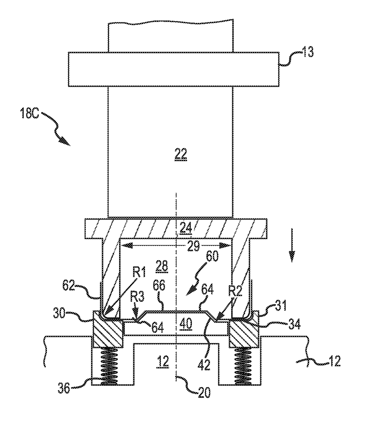
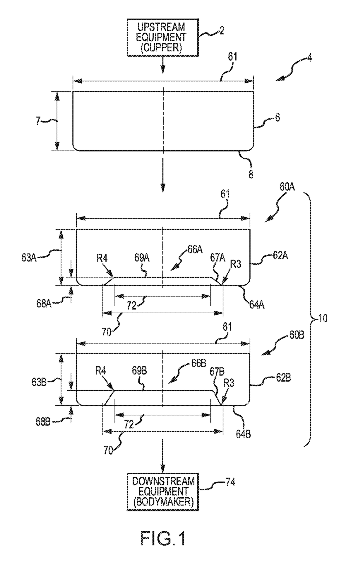
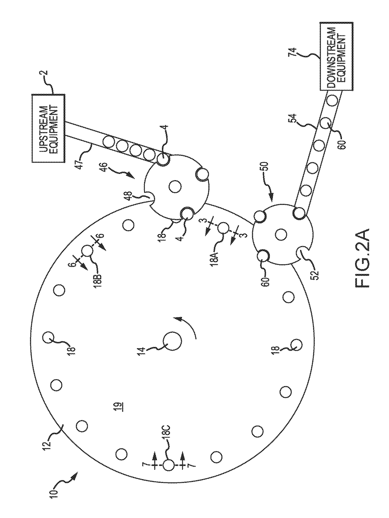
[0064]The present invention has significant benefits across a broad spectrum of endeavors. It is the Applicant's intent that this specification and the claims appended hereto be accorded a breadth in keeping with the scope and spirit of the invention being disclosed despite what might appear to be limiting language imposed by the requirements of referring to the specific examples disclosed. To acquaint persons skilled in the pertinent arts most closely related to the present invention, a preferred embodiment that illustrates the best mode now contemplated for putting the invention into practice is described herein by, and with reference to, the annexed drawings that form a part of the specification. The exemplary embodiment is described in detail without attempting to describe all of the various forms and modifications in which the invention might be embodied. As such, the embodiments described herein are illustrative, and as will become apparent to those skilled in the arts, may be...


PUM


Abstract

An apparatus and method for forming a deboss in a closed end-wall of a metallic cup is provided. The deboss apparatus generally includes a rotatable turret with tooling assemblies. The tooling assemblies are configured to receive a metallic cup formed by upstream equipment. The metallic cup formed by the upstream equipment has a closed end-wall that is generally planar. As the turret rotates, the tooling assemblies are configured to form a deboss in the closed end-wall of the metallic cup. In one embodiment, the deboss projects inwardly into an interior of the metallic cup. The metallic cup with a deboss is subsequently stripped from the tooling assembly for further processing.

Description

CROSS-REFERENCE TO RELATED APPLICATIONS[0001]This application claims priority under 35 U.S.C. § 119(e) to U.S. Provisional Patent Application Ser. No. 62 / 436,177 filed Dec. 19, 2016, which is incorporated herein in its entirety by reference.FIELD OF THE INVENTION[0002]The present invention relates generally to the manufacturing of metallic containers. More specifically, the present invention relates to a method and apparatus for forming a deboss in a closed end-wall of a metallic cup to enhance performance during subsequent operations in which the metallic cup is formed into a metallic container.BACKGROUND[0003]Metallic containers offer distributors and consumers many benefits. The body of a metallic container provides optimal protection properties for products. For example, the metallic body prevents CO2 migration and transmission of UV radiation which may damage the contents, such as beverages or other consumable products, negatively influencing the flavor, appearance, or color of...

Claims


Application Information

Patent Timeline
IPC IPC(8): B21D51/26
CPCB21D51/2607B21D51/26
Inventor ROBINSON, GREG
Owner BALL CORP
Learn More