Method and apparatus for controlling an operation performed on a continuous sheet of material

a continuous sheet of material and control method technology, applied in the direction of total factory control, programme control, electric programme control, etc., can solve the problems of requiring an undesirably large inventory of tools for different, affecting the operation of the container, etc., to achieve the effect of fast, reliable, and cost-effectiv

Active Publication Date: 2019-09-24
BALL CORP
View PDF107 Cites 0 Cited by
  • Summary
  • Abstract
  • Description
  • Claims
  • Application Information

AI Technical Summary

Benefits of technology

[0014]The present invention provides systems and methods for forming and / or marking continuous sheets of material (including tab stock that is subsequently formed into tabs) in a cost-effective, fast, and reliable manner. The marked tab stock is subsequently formed into pull tabs that can be interconnected to a container end closure by a conversion press.
[0015]One aspect of the present invention is to provide a system and method that increases the time available to perform an operation on a continuous sheet of material without reducing the cycle rate of other equipment in a coil fed production process. The system can include a servo feed unit that can move the continuous sheet of material into a zone where the operation is performed at a rate faster than the other equipment in the coil fed production process. Thus, more time is provided to perform the operation without slowing the other equipment in the production process. In one embodiment, the operation comprises forming a mark or indicia on the continuous sheet of material. Optionally, a laser can be used to form the mark on the continuous sheet. Accordingly, by increasing the time available for the laser to form the mark, more complex graphics, letters, numbers, and the like can be formed. Alternatively, by increasing the time available, the laser can form the mark at a lower power setting, thereby reducing operating costs. In another embodiment, the operation comprises one or more of a cutting, a punching, a shaping, and / or a forming step on a predetermined portion of the continuous sheet of material. In one embodiment, the continuous sheet of material is aluminum tab stock.
[0016]In one embodiment, the system can include a sensor to determine a position of the mark or indicia on the continuous sheet of material. In one embodiment, the sensor is a camera. If the mark is not in a predetermined position on the continuous sheet of material, the system can adjust a length of the continuous sheet of material fed into the zone where the operation is performed to assure proper positioning. More specifically, if the mark is too close to an upstream side of a portion of the continuous sheet of material, the servo feed unit can feed a decreased length of the continuous sheet of material into the operation zone. Alternatively, if the mark is too close to a downstream side of the portion of the continuous sheet of material, the servo feed unit can feed an increased length of the continuous sheet of material into the operation zone. In this manner, subsequent marks are formed in the corrected position.

Problems solved by technology

However, container bodies and the markings thereon are frequently obstructed during use of the container, such as by the consumer's hand during consumption of a beverage from a beverage container.
Embossing or incising, via stamping, can require an undesirably large inventory of tools for different kinds of lettering or symbols forming the marks.
Further, embossing or incising processes typically require the need to shut down an assembly line or conversion press to disassemble the conversion press whenever it is necessary to replace tools for maintenance or repairs or to change the mark being incised or embossed.
Such shutdowns are particularly troublesome when it is desirable to change the marks with relatively high frequency, such as when markings on containers or tabs are intended to be used as part of a contest or sweepstakes in which there are preferably a relatively large number of different possible markings or indicia.
Furthermore, it is difficult to accurately control the depth of embossing or incising and, in some cases, embossing or incising that is too deep may lead to leakage or container / end closure failure.
However, contact printing is believed impractical for many components, such as tabs, because of the shape or position of the tab.
Contact printing is also inefficient when it is desired to change the marks with relatively high frequency because of the need to stop a production line and at least partially disassemble the contact print device in order to change the configuration of the markings being printed on the tabs.
Although inkjet equipment can be controlled to provide changes in markings, inkjet processes and equipment have been found to be relatively unreliable and to require frequent maintenance and repair.
Inkjet processes have also been found to be subject to unwanted placement or positioning of ink.
For example, inkjet printing can result in a mist of ink which can interfere with the printing process, cause undesired markings on containers, or cause equipment malfunction.
In some cases, the use of an inkjet process can result in the loss of up to 20% or more of potential production time due to the need for clean up, maintenance, and / or repair.
It has also been found difficult to achieve reliable adhesion of the ink to containers or container components.
Additionally, inkjet processes have been difficult to provide at high speed without slowing the conversion press and while maintaining print quality to mark letters or other indicia without distortion.
Accordingly, inkjet and other printing processes are generally inappropriate for use in connection with contest sweepstakes or to provide other valuable tokens or indicia as there is an undesirably large potential for counterfeiting or altering of the markings in an attempt to claim a contest or sweepstakes prize.
Some or all of the above difficulties in previous container marking systems and methods are particularly troublesome for metallic containers or container components such as typical aluminum alloy beverage containers and tabs.
As compared with plastic or other container materials, metallic containers can be relatively difficult to mark, at least because it can be difficult to adhere ink to metal surfaces, because of the harder surfaces of metallic containers, and because of the higher melting or softening point of the metal material of the metallic containers.
Accordingly, devices and processes used in connection with some container materials are not necessarily applicable to others.
Further, in most situations, the functions or purposes of markings placed on metallic containers will rarely justify use of different methods and apparatus which would involve expenses that are substantially in excess of those involved with current methods and apparatus or that require operating the production line at a slower speed.
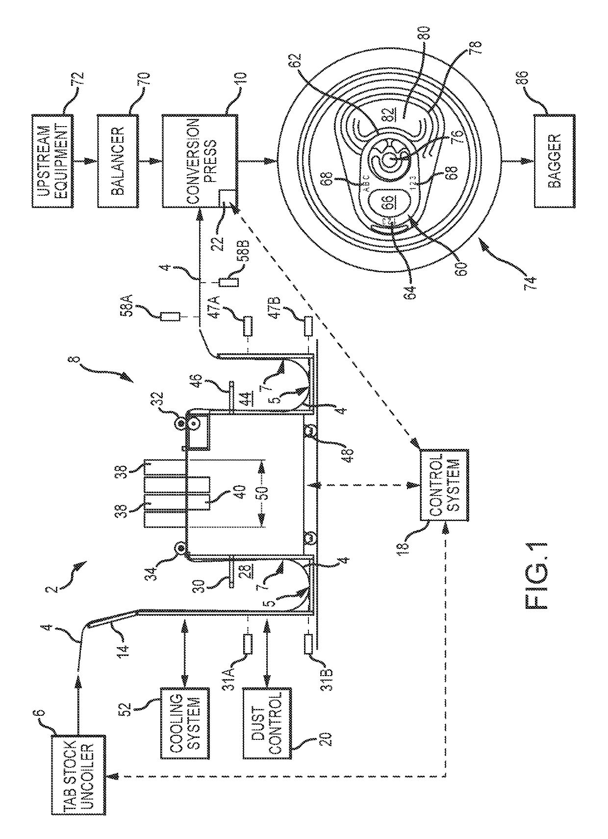
However, the system is directly integrated to the conversion press and cannot operate out of phase with the conversion press.
Because the system cannot run independently of the feed rate of the conversion press, the available laser print times are limited and cannot be increased without reducing the speed of the conversion press.
These methods of marking tabs are generally considered to be unsuitable as the lacquers added to the tab unacceptably increase the productions costs of tabs substantially in excess of those involved with current processes.
However, the energy required to power lasers of these strengths makes their use uneconomical in an end closure manufacturing process where several hundred thousand or millions of tabs are manufactured daily.

Method used


Image

  • Method and apparatus for controlling an operation performed on a continuous sheet of material
  • Method and apparatus for controlling an operation performed on a continuous sheet of material
  • Method and apparatus for controlling an operation performed on a continuous sheet of material

Examples


Embodiment Construction

[0084]The present invention has significant benefits across a broad spectrum of endeavors. It is the Applicant's intent that this specification and the claims appended hereto be accorded a breadth in keeping with the scope and spirit of the invention being disclosed despite what might appear to be limiting language imposed by the requirements of referring to the specific examples disclosed. To acquaint persons skilled in the pertinent arts most closely related to the present invention, a preferred embodiment that illustrates the best mode now contemplated for putting the invention into practice is described herein by, and with reference to, the annexed drawings that form a part of the specification. The exemplary embodiment is described in detail without attempting to describe all of the various forms and modifications in which the invention might be embodied. As such, the embodiments described herein are illustrative, and as will become apparent to those skilled in the arts, may be...


PUM

PropertyMeasurementUnit
lengthaaaaaaaaaa
heightaaaaaaaaaa
heightaaaaaaaaaa

Abstract

A system and method of performing an operation on a continuous sheet of stock material is provided. More specifically, the present invention relates to a system and method used to perform an operation on a continuous sheet of stock material in a high speed manufacturing system. The continuous sheet of stock material can subsequently be received by a second system that performs a different operation on the continuous sheet of stock material. In one embodiment, the second system forms the continuous sheet of stock material into tabs for container end closures. The system can include an infeed accumulation device and an outfeed accumulation device. The infeed and outfeed accumulation devices enable the system to operate at a variable rate and out of phase with a high speed, coil fed manufacturing system to which the system may be removably integrated. The system can determine if the operation has been performed in at a predetermined location of a portion of the continuous sheet of stock material.

Description

CROSS-REFERENCE TO RELATED APPLICATIONS[0001]This application is a Continuation-in-Part application of, and claims priority to, U.S. patent application Ser. No. 15 / 130,319, filed on Apr. 15, 2016, entitled “Method and Apparatus for Controlling the Speed of a Continuous Sheet of Material,” now U.S. Pat. No. 10,073,443, which claims priority under 35 U.S.C. § 119(e) to U.S. Provisional Patent Application Ser. No. 62 / 149,079 filed Apr. 17, 2015, which is incorporated herein in its entirety by reference.FIELD OF THE INVENTION[0002]The present invention relates generally to the manufacture of container end closures. More specifically, the present invention relates to a system and method of controlling the speed of a continuous sheet of material, and more specifically, of tab stock. The system can operate out of phase with a high speed, coil fed end closure manufacturing system to which the tab manufacturing and marking system is removably integrated.BACKGROUND[0003]As part of container m...

Claims


Application Information

Patent Timeline
Patent Type & Authority Patents(United States)
IPC IPC(8): B21D22/00G05B19/418B21D47/00
CPCG05B19/41865B21D22/00B21D47/00G05B2219/31376Y10T29/49787Y10S220/906Y02P90/02B23K26/0846B23K2101/16
Inventor GORSUCH, JASON E.ANDERSON, KENNETH D.CRISMAN, ALEX V.STOKES, THOMAS J.BEGEMAN, BRADLEY ROY
Owner BALL CORP
Why Eureka
Try Eureka