Tool including dummy chip

Active Publication Date: 2018-01-18
SANDVIK INTELLECTUAL PROPERTY AB
View PDF5 Cites 0 Cited by
  • Summary
  • Abstract
  • Description
  • Claims
  • Application Information

AI Technical Summary

Benefits of technology

The patent relates to a tool that can be rotated to improve balance. The tool has a cavity where a dummy chip is placed to help achieve a balanced rotation. Additionally, the tool may also have an ID chip with the same mass as the dummy chip, which further improves the balancing properties. This allows for smoother and more precise machining.

Problems solved by technology

However, it has the disadvantage that it is not rotationally balanced when an ID chip is mounted in one of the bore holes.

Method used


Image

  • Tool including dummy chip
  • Tool including dummy chip
  • Tool including dummy chip

Examples


Embodiment Construction

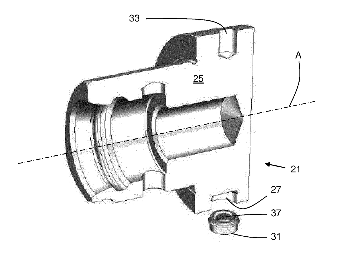
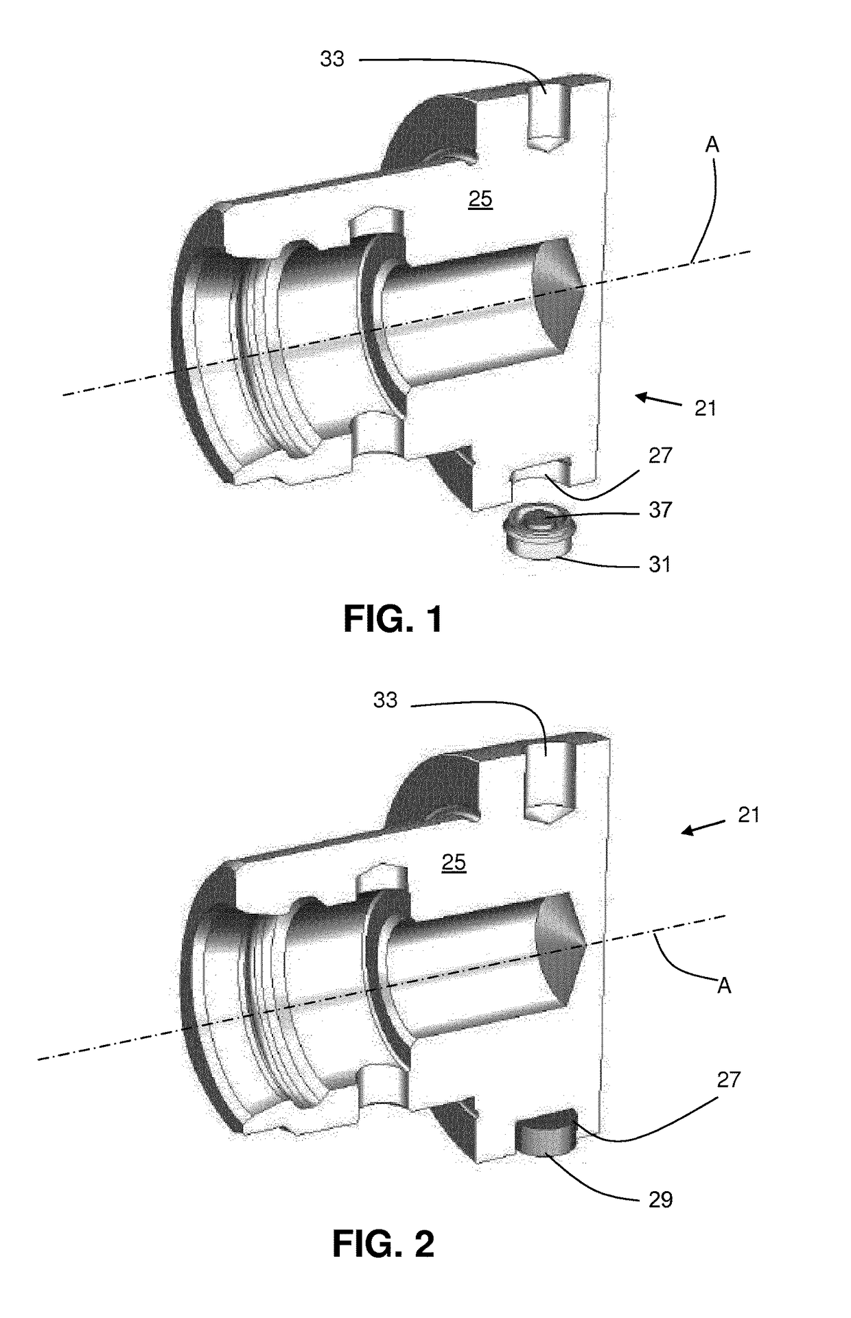
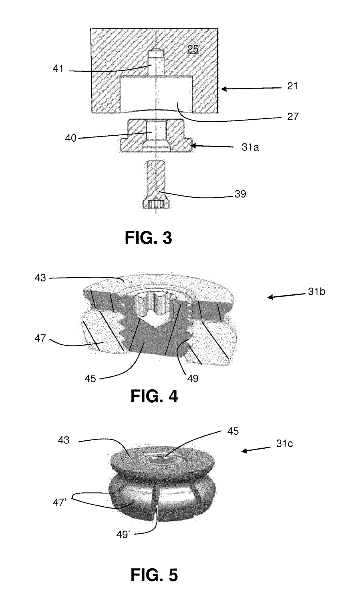
[0037]A rotatable tool 21 in FIG. 1 and comprises a tool body 25 having an axis A of rotation and a first recess 27 having a first exterior geometry in which a dummy chip 31 can be secured. The dummy chip 31 comprises a counterweight member 37. The counterweight member 37 is located in a recess in the dummy chip 37. The counterweight member 37 is made from steel. The dummy chip 31 comprises a radially compressible plastic body having a ridge, which permits the dummy chip 31 to be received in the first recess 27 and secured in an internal radial groove in the first recess 27. The dummy chip 31 is not capable of storing data electronically. It can have data in the form of a printed text or symbols. The tool 21 includes a second recess 33 for rotationally balancing the tool while the dummy chip 31 is in the first recess 27. The second recess 33 is disposed on a geometrically opposite side of the tool 21 from the first recess 27, centered at the same position along the axis A. The secon...


PUM

PropertyMeasurementUnit
Centrifugal forceaaaaaaaaaa
Massaaaaaaaaaa
Elasticityaaaaaaaaaa

Abstract

A rotating tool includes a tool body having an axis of rotation and a first recess for receiving an ID chip having a first mass and a first exterior geometry. The tool includes a dummy chip receivable in the first recess and the tool is rotationally balanced with the dummy chip in the first recess, wherein after balancing the dummy chip is removed and the ID chip is insertable in the first recess.

Description

BACKGROUND AND SUMMARY[0001]The present invention relates to tools of the type including ID chips. Especially, this invention relates to rotating tools, such as drilling, milling or boring tools or extension tools which are adapted to hold such tools, for use in CNC-machines in metal cutting operations.[0002]U.S. Patent App. Pub. US2006 / 0127197A1 describes tools of the type having ID (identification) chips mounted thereon. Such ID chips are useful for various purposes, such as tool inventory, maintenance, and the like and permit identification of a tool without the need for visual or physical contact with identification means. ID chips are also called ID tags, and comprise a data—or information carrier and wireless transmitting means, more specifically the ID chip is arranged to electronically store data and this data is possible to read on an external unit wirelessly. Common forms of ID chips are RFID-chips, where RFID stands for radio frequency identification.[0003]When using such...

Claims


Application Information

Patent Timeline
IPC IPC(8): B23C5/00
CPCB23C5/006B23B2231/10B23B2250/04B23B2270/36B23C2250/04B23C2250/16
Inventor KOERNER, ULRICH
Owner SANDVIK INTELLECTUAL PROPERTY AB
Why Eureka
Try Eureka