Assembly for controlling variable pitch vanes in a turbine engine

a turbine engine and variable pitch technology, which is applied in the direction of machines/engines, stators, liquid fuel engines, etc., can solve the problems of increasing the overall dimensions of the variable pitch assembly, increasing the fuel consumption of the turbine engine, and different angular pitch of the vanes, so as to achieve simple, efficient and cost-effective

Active Publication Date: 2018-01-18
SN DETUDE & DE CONSTR DE MOTEURS DAVIATION S N E C M A
View PDF2 Cites 4 Cited by
  • Summary
  • Abstract
  • Description
  • Claims
  • Application Information

AI Technical Summary

Benefits of technology

[0008]The invention more particularly aims at providing a si

Problems solved by technology

This deflection must be prevented at all costs, since it results in greater displacement of the rods of the vanes located in this portion, resulting in a different angular pitch for the vanes.
Indeed, a second driving means adds an additional mass that results in an increase in fuel consumption of the turbine engine.
Furthermore, the presence of a second driving means increases the overall dimensions of the var

Method used


Image

  • Assembly for controlling variable pitch vanes in a turbine engine
  • Assembly for controlling variable pitch vanes in a turbine engine
  • Assembly for controlling variable pitch vanes in a turbine engine

Examples


Embodiment Construction

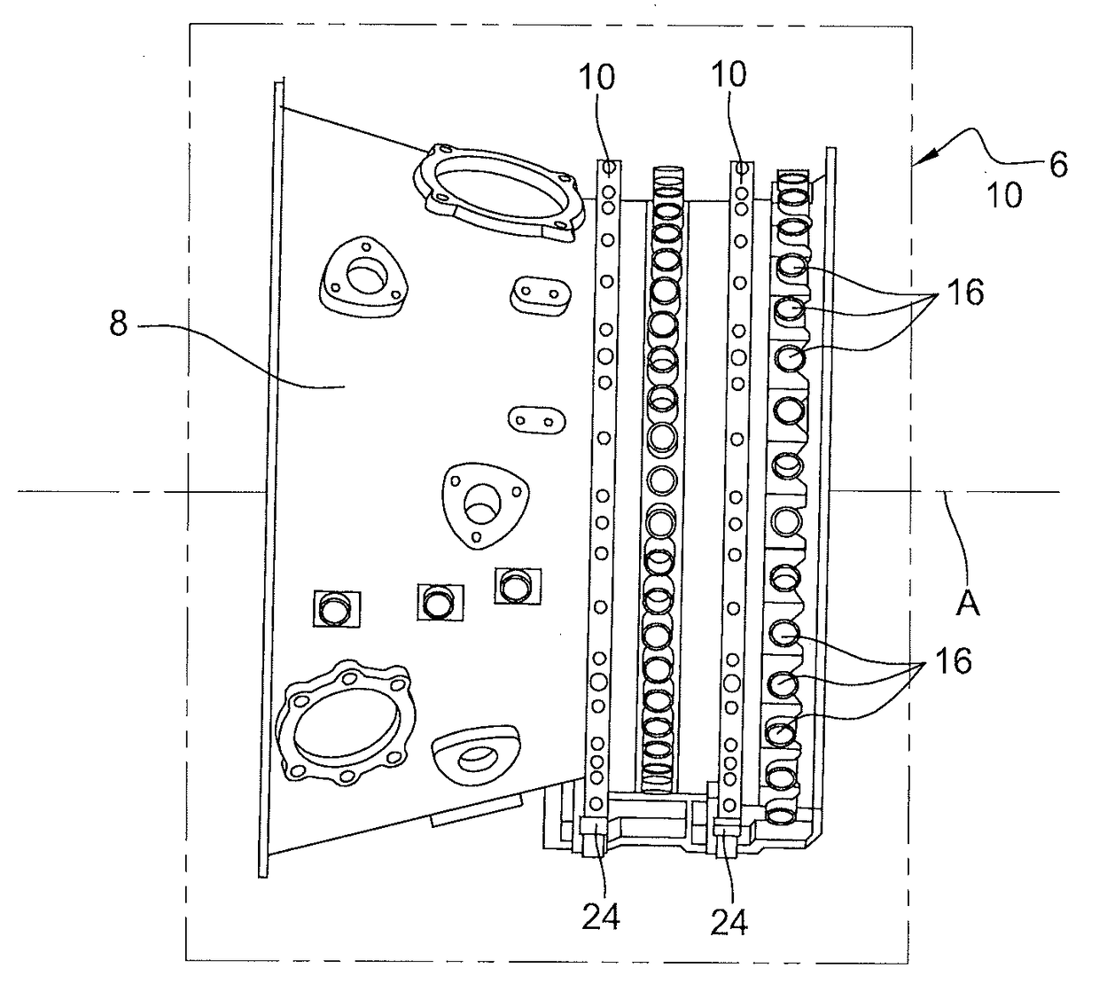
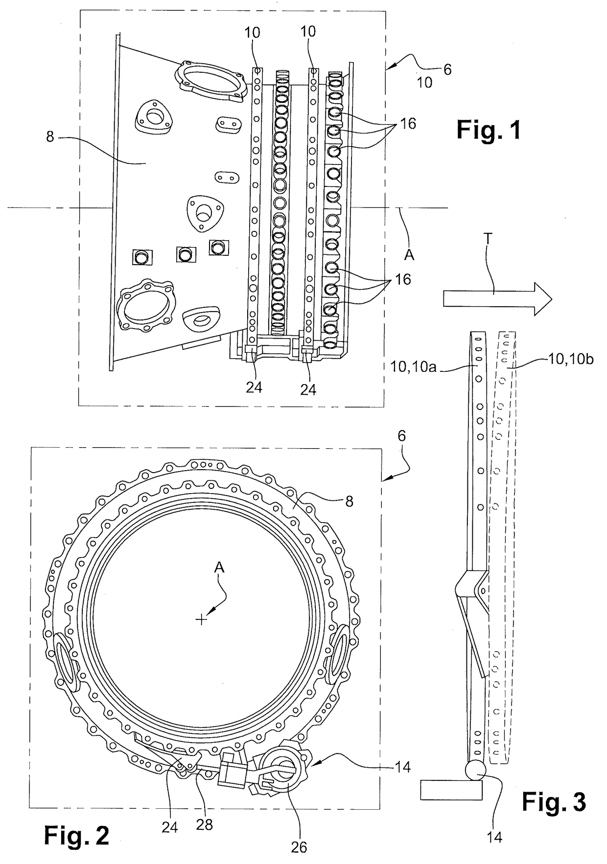
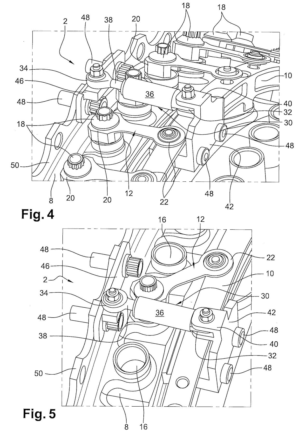
[0027]Illustrated in the figures is an assembly 2, particularly for controlling variable pitch vanes 4 in a turbine engine 6, comprising a casing 8 of the turbine engine 6, an actuating ring 10 surrounding the casing 8 and connected by rods 12 to the variable pitch vanes 4 and a driving means 14 for rotating the actuating ring 10 around the casing 8. Preferably, the casing 8 is annular and has a longitudinal axis A of symmetry and the actuating ring 10 is coaxial with the casing 8 and mounted around the latter. In the example illustrated in the figures and particularly in FIG. 1, two rings 10 are represented; however, reference will only be made to a single ring 10 in the further description, given that all the actuating rings 10 are identical and function in the same manner.

[0028]The casing 8 has shafts 16 in which nuts 18 integral with the vanes 4 are fixed, said nuts 18 defining an axis A1 of rotation of the vanes 4 to adjust their pitch.

[0029]The rods 12 are integral at a first ...


PUM


Abstract

An assembly, in particular for controlling variable pitch vanes in a turbine engine, comprising an actuating ring surrounding a casing of the turbine engine and connected by rods to variable pitch vanes, in addition to a driving means for rotating the actuating ring around the casing. The assembly includes a slidingly connected passive element, one end of which is connected by a sliding pivoting link on the actuating ring and a second end is connected by a ball-joint link to the casing.

Description

BACKGROUND OF THE INVENTION1. Field of the Invention[0001]The present invention relates to an assembly for a turbine engine comprising variable pitch vanes in addition to a turbine engine comprising said assembly.2. Description of the Related Art[0002]Conventionally, an assembly for variable pitch vanes comprises a shroud in which the vanes are mounted for rotation around their own axis, wherein the orientation of the vanes is known as the pitch.[0003]To control the pitch of the blades, it is known to use an actuating ring coaxial to the shroud around a longitudinal axis of the turbine engine and connected to the pivot of each of the vanes by rods integral with said vane pivots. A driving means rotates the ring, around the shroud, which pivots the rods around their respective pivots, thereby allowing an angular pitch of the blades in relation to the air flow circulating inside the shroud.[0004]Due to the rigidity of the rods, the movement of the ring corresponds to the combination o...

Claims


Application Information

Patent Timeline
IPC IPC(8): F01D17/14F01D9/04F01D17/26
CPCF01D17/141F01D9/041F05D2220/323F05D2260/50F01D17/26F01D17/162F04D29/563Y02T50/60
Inventor BENDERRADJI, KAMELBERGAN, BLAISEBROMANN, ALAIN MARC LUCIENCOUSTILLAS, SUZANNE MADELEINEDUMAS, LILIAN YANN
Owner SN DETUDE & DE CONSTR DE MOTEURS DAVIATION S N E C M A
Why Eureka
Try Eureka