Optical device with a collimator and lenslet arrays

a technology of collimator and lenslet array, which is applied in the field of optical devices with collimators and lenslet arrays, can solve problems such as artefacts visible, and achieve the effect of increasing light intensity

Active Publication Date: 2018-01-18
SIGNIFY HLDG BV
View PDF8 Cites 6 Cited by
  • Summary
  • Abstract
  • Description
  • Claims
  • Application Information

AI Technical Summary

Benefits of technology

[0007]It would be advantageous to achieve an optical device overcoming, or at least alleviating, the above mentioned drawbacks. In particular, it would be desirable to achieve an optical device capable of emitting light forming a more narrow light beam and having a higher light intensity.

Problems solved by technology

Non-uniform light sources such that e.g. light emitting diode (LED) arrays and LEDs of different colours may hence cause artefacts visible in the resulting light beam and beam spot when combined with a collimator.

Method used


Image

  • Optical device with a collimator and lenslet arrays
  • Optical device with a collimator and lenslet arrays
  • Optical device with a collimator and lenslet arrays

Examples


Embodiment Construction

[0046]The present aspects will now be described more fully hereinafter with reference to the accompanying drawings, in which currently preferred embodiments are shown. This invention may, however, be embodied in many different forms and should not be construed as limited to the embodiments set forth herein; rather, these embodiments are provided for thoroughness and completeness, and fully convey the scope of the present aspect to the skilled person.

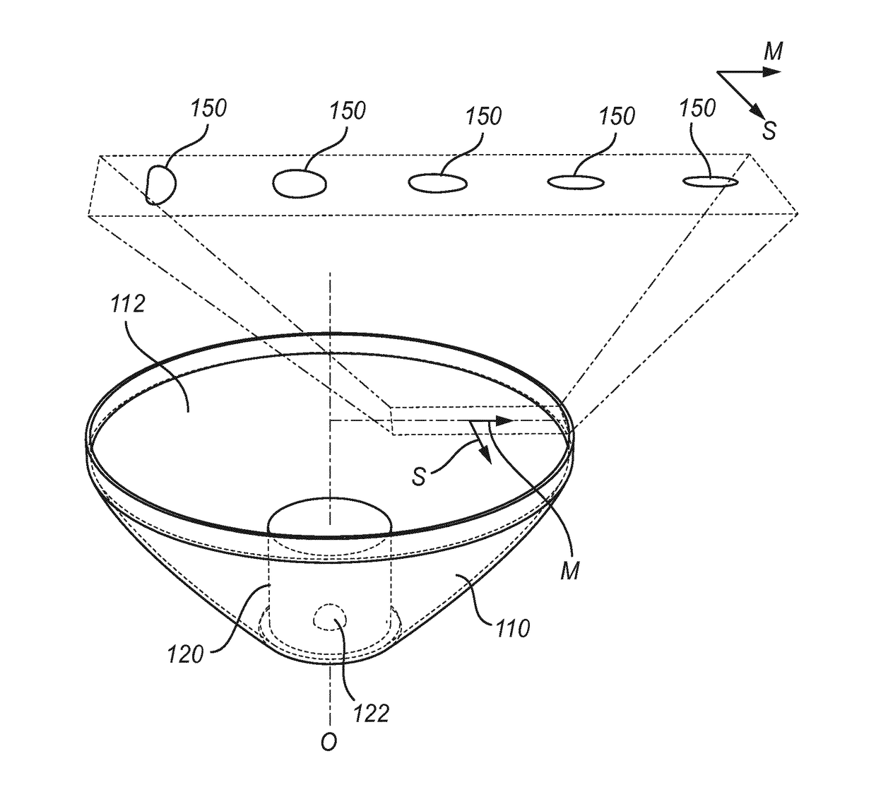
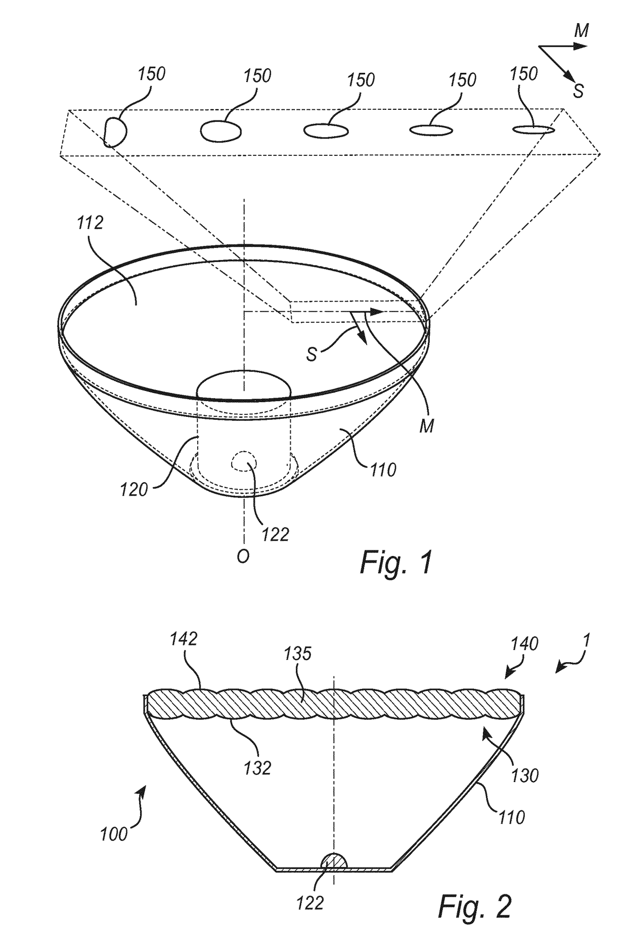
[0047]FIG. 1 is a perspective view of a collimator 110 of an optical device according to an embodiment. The collimator 110 may be rotationally symmetric around its optical axis O and arranged to collimate light from a light source 122 comprising e.g. a LED 122. The light source 122 may e.g. be arranged within a cavity 120, which e.g. may comprise light refracting cylindrical sidewalls and a refractive top surface that may face an exit opening 112 of the collimator 110 and be formed as a convex lens configured to focus light exiting throu...


PUM


Abstract

An optical device (100) is disclosed, comprising a collimator (110) and a first lenslet array (130, 430) and a second lenslet array (140, 440). The first lenslet array and the second lenslet array are provided with the same tessellation pattern, aligned with each other and arranged such that a projection (150) of a light source (122) is focused on the second lenslet array, which is configured to emit non-focused light. At least some of the lenslets of the second array are formed such that a ratio of their sagittal and meridional dimensions varies at least along the meridional direction (M) of the second lenslet array, based on the varying shape of the projection of the light source as seen by said lenslets, so as to achieve an improved mixing, intensity and uniformity of light emitted from the optical device.

Description

FIELD OF THE INVENTION[0001]The present invention generally relates to the field of illumination devices. More precisely, the invention relates to an optical device having a collimator and a first lenslet array and a second lenslet array arranged to receive collimated light, and to a method for manufacturing such device.BACKGROUND OF THE INVENTION[0002]There is a growing interest in new optical devices having an improved efficiency in terms of energy consumption, colour mixing and illumination uniformity. Collimators are known to be used in many illumination applications to produce a desired illumination pattern beam angle. However, many collimators tend to reproduce at least part of the spatial structure of the light source. Non-uniform light sources such that e.g. light emitting diode (LED) arrays and LEDs of different colours may hence cause artefacts visible in the resulting light beam and beam spot when combined with a collimator.[0003]Existing optical devices may therefore com...

Claims


Application Information

Patent Timeline
Patent Type & Authority Applications(United States)
IPC IPC(8): G02B3/00G02B19/00F21V5/00G02B27/30
CPCG02B3/0062G02B27/30G02B3/0068F21V5/007F21V5/008G02B3/0043G02B19/0061F21V5/04G02B3/0056G02B27/0927G02B27/0961G02B19/0028H01L33/58H01L31/0232
Inventor DROSS, OLIVER
Owner SIGNIFY HLDG BV
Why Eureka
Try Eureka