Computer program, head-mounted display device, and calibration method

a computer program and display device technology, applied in the field of spatial relationship calibration, can solve problems such as difficulty in making the two calibration methods individually successful

Active Publication Date: 2018-01-18
SEIKO EPSON CORP
View PDF0 Cites 12 Cited by
  • Summary
  • Abstract
  • Description
  • Claims
  • Application Information

AI Technical Summary

Benefits of technology

[0005]Technically, it is easy to make a time resolution of an inertial sensor higher than a time resolution (frame rate of an image) of a tracking camera. Consequently, as a measure of the above-mentioned latency, it is considered that it is effective to estimate the position and pose (a spatial positional re...

Problems solved by technology

As described above, it is preferable that two calibration methods are perfor...

Method used


Image

  • Computer program, head-mounted display device, and calibration method
  • Computer program, head-mounted display device, and calibration method
  • Computer program, head-mounted display device, and calibration method

Examples


Embodiment Construction

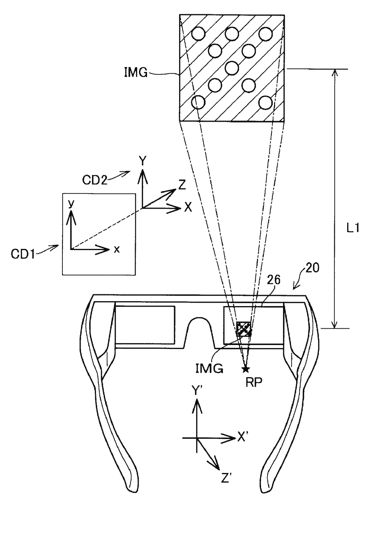
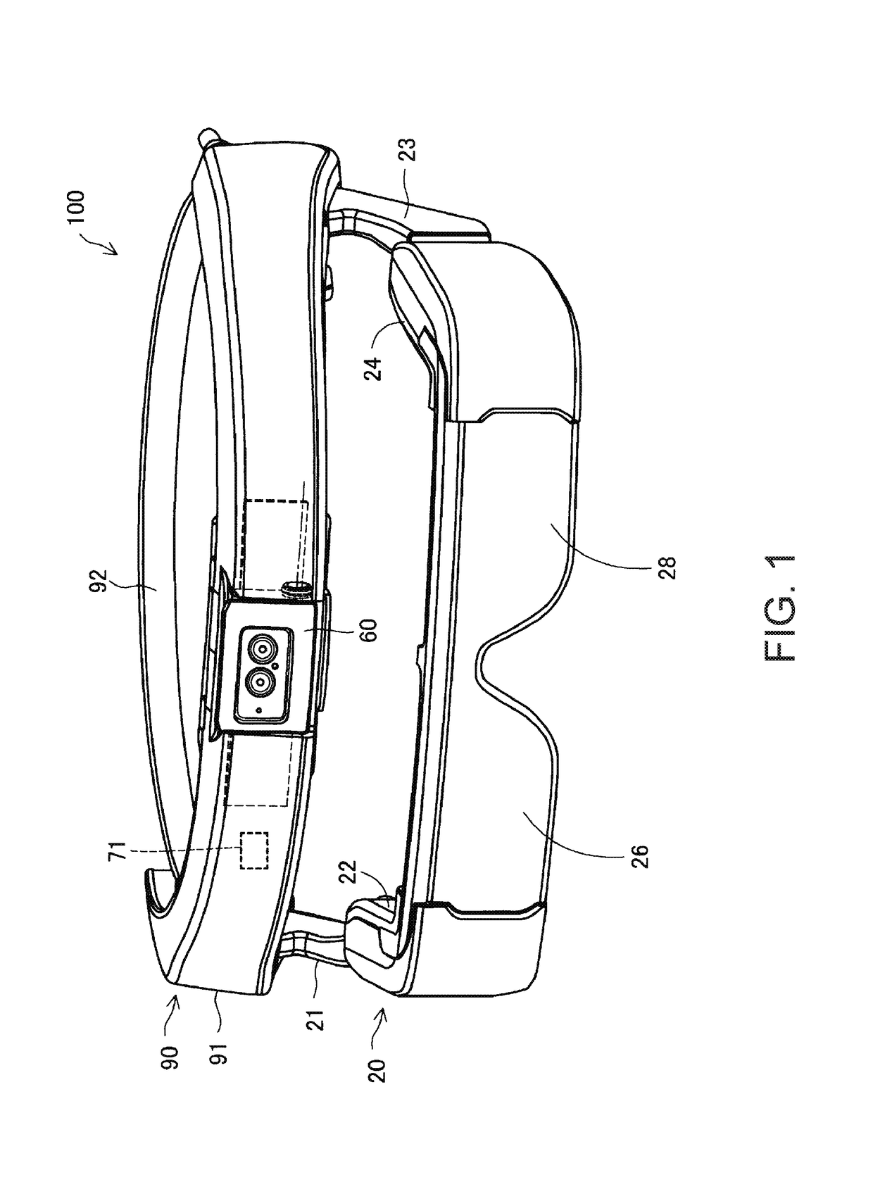
[0037]FIGS. 1 to 3 are diagrams illustrating an exterior configuration of a head-mounted display device 100 (HMD 100). The HMD 100 can make a user visually perceive a di play image displayed on an image display section 20 and can make the user visually perceive an outside scene by light from the outside scene passing through the image display section 20 (FIG. 1). Although a detailed configuration thereof will be described later, the HMD 100 according to the present embodiment includes image display sections corresponding to the right and left eyes of a user wearing the image display section 20 to thereby allow the user's right and left eyes to visually perceive separate images.

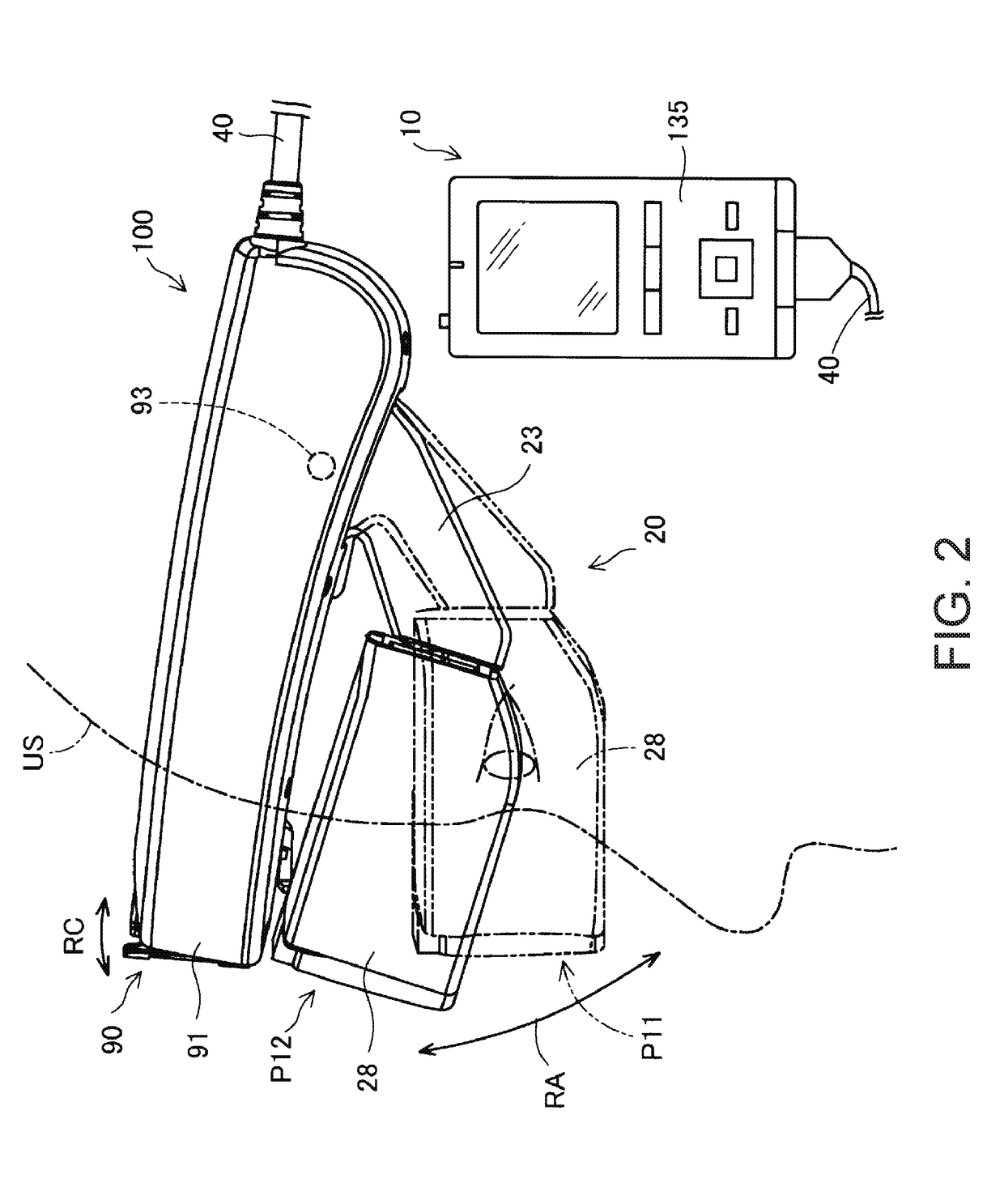
[0038]As illustrated in FIG. 2, the HMD 100 includes a mounting band 90 mounted on the head-mounted display device of a user, the image display section 20 connected to the mounting band 90, a control section 10 controlling the image display section 20, and a connection portion 40 connecting the control section...


PUM


Abstract

A method includes acquiring first and second images that are captured by imaging a first real marker with a camera when the camera is respectively at a first and second positions with respect to the first real marker, deriving a motion of an inertial sensor based on output of the inertial sensor when the camera moves from the first position to the second position, displaying a marker image corresponding to a second real marker on a display, acquiring a third image that is obtained by capturing the second real marker with the camera when a user perceives the marker image and the second real marker being aligned with each other, and deriving a first spatial relationship between the camera and the inertial sensor and a second spatial relationship between the camera and the display based at least on the first and second images, the motion, and the third image.

Description

BACKGROUND1. Technical Field[0001]The present invention relates to calibration of a spatial relationship.2. Related Art[0002]There has been known a head-mounted display device (hereinafter, also referred to as an HMD) which is worn on a user's head. For example, JP-A-2005-38321 discloses a video see-through type HMD in which an imaging section supported through a supporting section slides up and down with respect to a main body of the HMD.[0003]Hereinafter, an HMD including a tracking camera so as to be capable of providing an AR (augmented reality) function will be described as an example of a see-through type display device. The HMD detects the position of a real object with respect to the HMD (or a tracking camera) through a tracking camera, and tracks the real object (the tracking of a real object using this method is referred to as “optical tracking”) The HMD displays a virtual object such as CG so as to follow the position of the real object. At this time, a user visually perc...

Claims


Application Information

Patent Timeline
IPC IPC(8): G02B27/01
CPCG06T7/80G02B27/0172G06T2207/20221G06T2207/30204G06T7/337G02B2027/0178G02B2027/0138G02B27/0176
Inventor GUOYI, FU
Owner SEIKO EPSON CORP
Why Eureka
Try Eureka