Leading edge systems and methods for aerospace vehicles

a technology for aerospace vehicles and leading edges, applied in the field of can solve problems such as damage to thermally insulating tiles, adversely affecting the leading edges of aerospace vehicles, aerospace vehicles such as aircraft, and aircraft may experience damage to the leading edges of wings or other surfaces

a technology for aerospace vehicles and leading edges, applied in the field of can solve problems such as damage to thermally insulating tiles, adversely affecting the leading edges of aerospace vehicles, aerospace vehicles such as aircraft, and aircraft may experience damage to the leading edges of wings or other surfaces

US20180022439A1Active Publication Date: 2018-01-25THE BOEING CO

Image

  • Leading edge systems and methods for aerospace vehicles
  • Leading edge systems and methods for aerospace vehicles
  • Leading edge systems and methods for aerospace vehicles

Examples


Embodiment Construction

[0043]Disclosed embodiments will now be described more fully hereinafter with reference to the accompanying drawings, in which some, but not all of the disclosed embodiments are shown. Indeed, several different embodiments may be provided and should not be construed as limited to the embodiments set forth herein. Rather, these embodiments are provided so that this disclosure will be thorough and fully convey the scope of the disclosure to those skilled in the art.

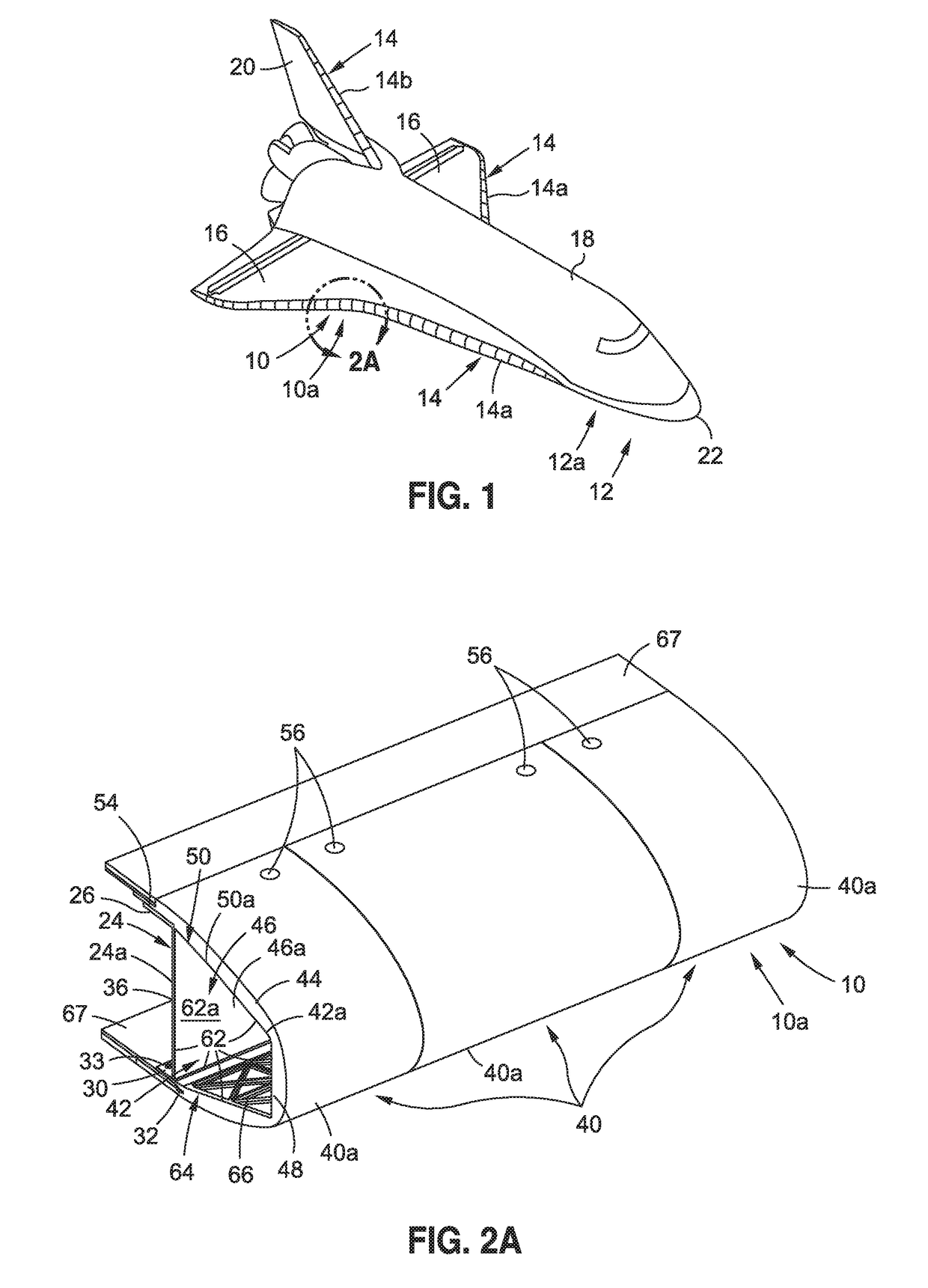
[0044]Now referring to the Figures, FIG. 1 is an illustration of a front perspective view of an exemplary aerospace vehicle 12, such as in the form of an aircraft 12a, having an exemplary embodiment of a leading edge system 10, such as in the form of leading edge system 10a, of the disclosure. In one embodiment, the aerospace vehicle 12 (see FIG. 1) is configured to travel at an altitude of 350,000 feet or less, and preferably, at an altitude of 150,000 feet or less, and comprises the aircraft 12a (see FIG. 1), an unmanned ...


PUM


Abstract

There is provided a leading edge system for an aerospace vehicle. The leading edge system has at least one structural member. The leading edge system further has a plurality of removable modules removably attached to the at least one structural member. Each removable module has a hollow box substructure and at least one flange portion disposed along a first end of the hollow box substructure. The leading edge system further has a plurality of first attachment elements configured for attaching the at least one flange portion of the removable module to a first end portion of the at least one structural member. The leading edge system further has a plurality of second attachment elements configured for attaching a second end of the hollow box substructure opposite the flange portion, to a second end portion of the at least one structural member opposite the first end portion.

Description

BACKGROUND[0001]1) Field of the Disclosure[0002]The disclosure relates generally to systems and methods for aerospace vehicle parts, and more particularly, to systems and methods relating to leading edges of aerospace vehicles, such as spacecraft, aircraft, hypersonic vehicles, unmanned aerial vehicles (UAVs), missiles, and other aerospace vehicles.[0003]2) Description of Related Art[0004]Aerospace vehicles travelling through Earth's atmosphere and through space may be exposed to extreme temperatures or environmental events which may adversely affect leading edges of the wings, tail, or other surfaces of the aerospace vehicle. For example, aerospace vehicles, such as spacecraft, typically have a thermal protection system (TPS) that includes thermally insulative tiles to insulate the leading edges of the wings and other surfaces of the spacecraft from the environment and to radiate and reflect heat from the spacecraft. When the spacecraft re-enters Earth's atmosphere from space at hy...

Claims


Application Information

Patent Timeline
25 Jan 2018
Publication
US20180022439A1
IPC
B64C3/36; B64G1/58; B64C39/02; B64C3/18
CPC
B64C3/36; B64C3/185; B64C39/024; B64C3/182; B64G1/58; B64C3/187; B64C1/38; B64G1/62
Inventors
STANLEY, DANIEL C.; KRUSE, JOHN S.