Crop engaging element for a combine harvester separating rotor

a technology of separating rotor and crop, which is applied in the direction of mowers, agricultural tools and machines, and mowers, etc., can solve the problems of reducing the chance of crop material getting stuck on the entry point of the crop engaging finger, and the risk of the finger element twisting under high loads, so as to improve the design of the crop engaging element and improve the performance of the separating rotor. , the effect of reducing power consumption

Active Publication Date: 2018-02-01
AGCO INT GMBH
View PDF3 Cites 3 Cited by
  • Summary
  • Abstract
  • Description
  • Claims
  • Application Information

AI Technical Summary

Benefits of technology

[0004]It is an object of the invention to improve the design of the crop engaging elements with a view to improving t

Problems solved by technology

The flared edge, and the resultant reduced angle between the leading corner of the base edge and the rotor tube reduces the abruptness by which the crop material is lifted from the surface of the rotor tube for rearward co

Method used


Image

  • Crop engaging element for a combine harvester separating rotor
  • Crop engaging element for a combine harvester separating rotor
  • Crop engaging element for a combine harvester separating rotor

Examples


Embodiment Construction

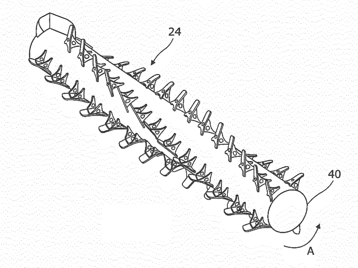
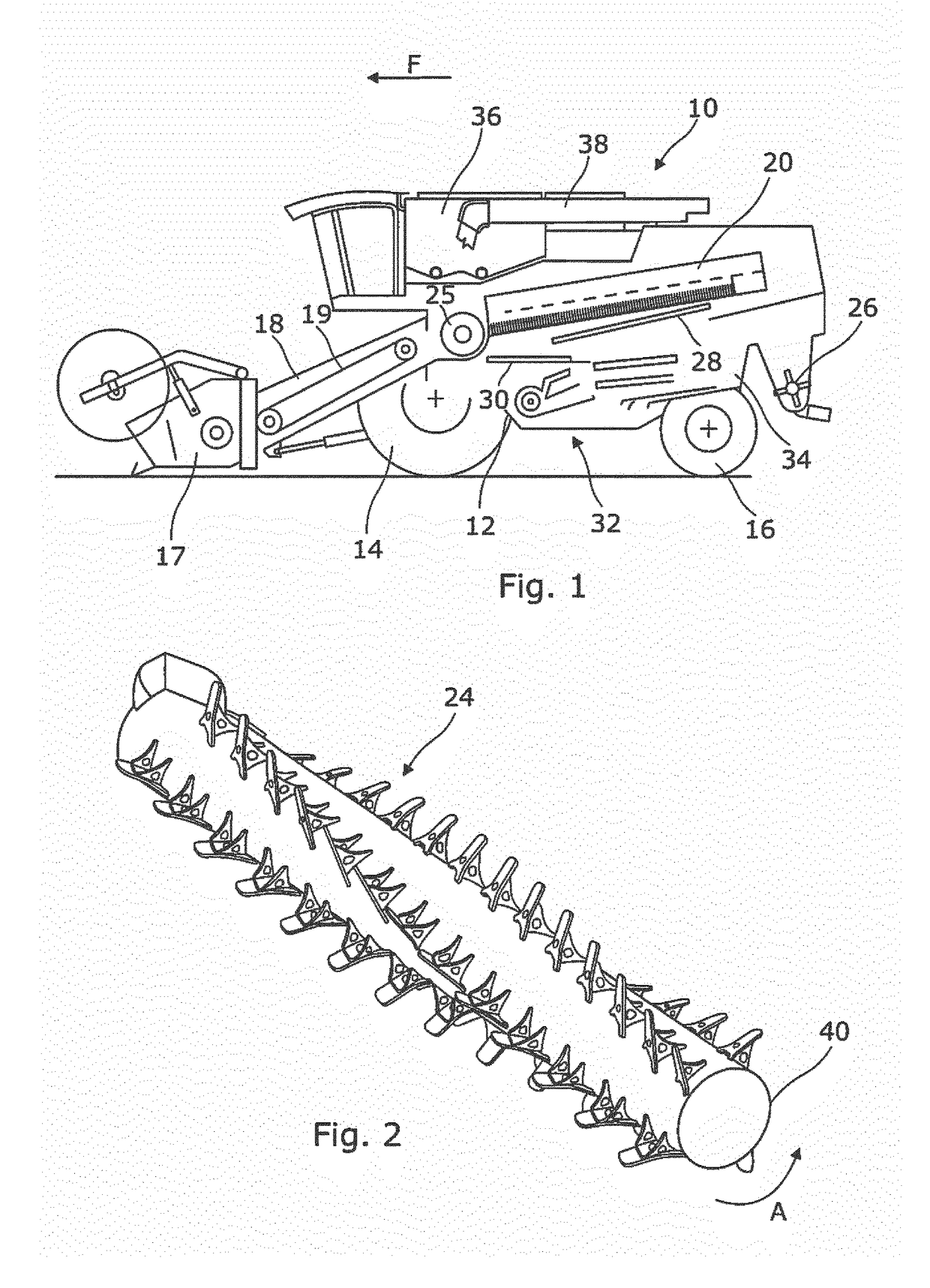
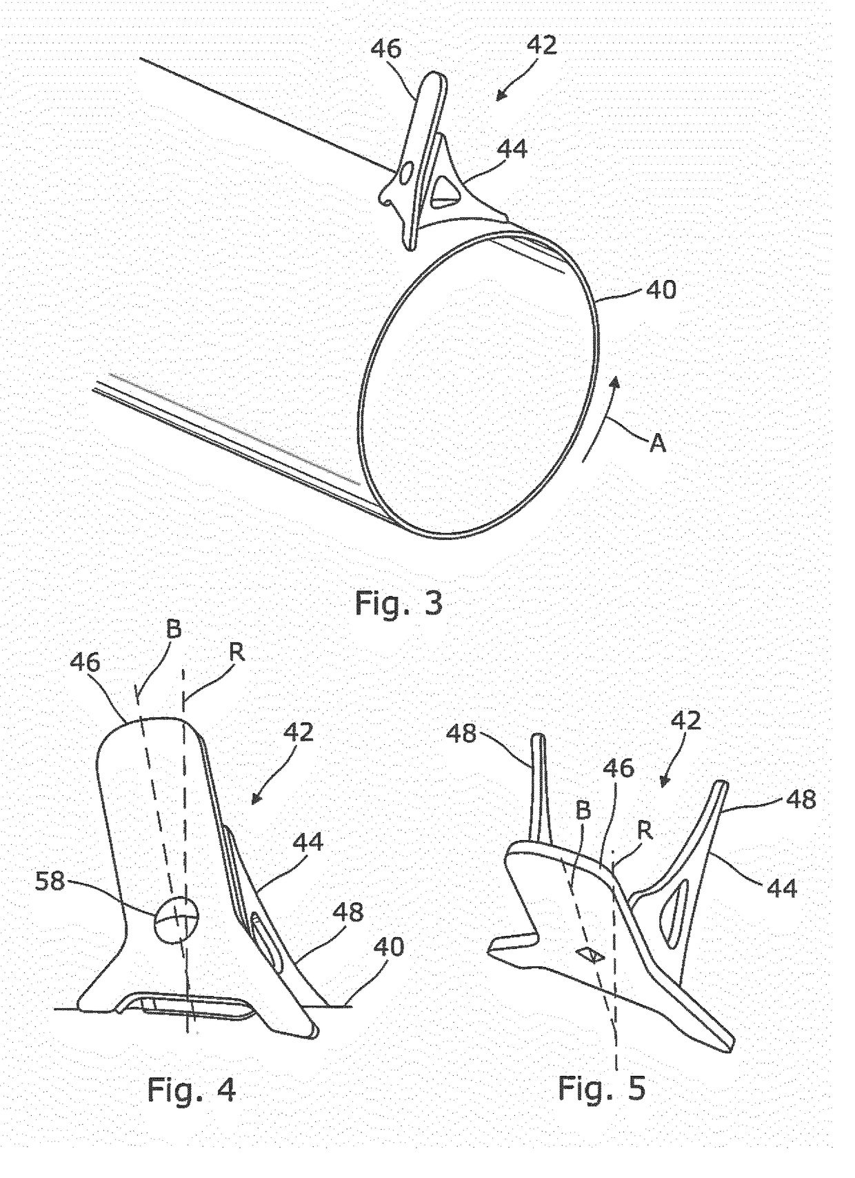
[0024]An example embodiment of the invention will now described. Relative terms such as ‘front’, ‘rear’, ‘left’, ‘right’, ‘longitudinal’ and ‘transverse’ will be made with reference to the longitudinal axis of a combine harvester travelling in the normal forward direction of travel indicated by arrow F in FIG. 1. The terms ‘direction of conveyance’, ‘upstream’, and ‘downstream’ are made with reference to the general flow of crop material through the combine harvester. The terms ‘axial’, ‘radial’ and ‘tangential’ will be used in relation to the rotation axis of the rotor.

[0025]With reference to FIG. 1 a combine harvester 10 includes a frame 12, front wheels 14 and rear steerable wheels 16. A cutting header 17 is detachably supported on the front of a feederhouse 18 which is pivotable about a transverse axis to lift and lower the header 17 in a conventional manner.

[0026]The combine 10 is driven in a forward direction F across a field of standing crop in a known manner. The header 17 s...


PUM


Abstract

A combine harvester with a separating rotor, rotor tube and a plurality of crop engaging finger elements. Each finger element is mounted to a respective finger support which is secured to the rotor tube. Each finger element has a planar body with a flared base portion which presents a leading edge to the crop material with a relatively shallow angle with respect to the tube.

Description

FIELD OF INVENTION[0001]The invention relates to combine harvester grain separating systems and particularly to axial flow separating rotors comprising a rotor tube and a plurality of crop engaging elements secured to the rotor tube.BACKGROUND[0002]For many decades self-propelled combine harvesters have been used by farmers to harvest a wide range of crops including cereals, maize and oil seed rape. Typically a combine harvester cuts the crop material, threshes the grain therefrom, separates the grain from the straw and cleans the grain before storing in an on-board tank. Straw and crop residue is ejected from the rear of the machine.[0003]The crop processor of a combine harvester comprises threshing and separating apparatus. The separating apparatus is traditionally based upon one of two well-established systems. In a first known system straw walkers are used to ‘walk’ the crop stream rearwardly in the combine wherein agitation caused by this movement causes the grain to fall throu...

Claims


Application Information

Patent Timeline
IPC IPC(8): A01F12/22A01F12/395A01F7/06
CPCA01F12/22A01F7/06A01F12/395A01F12/446A01F12/46A01D41/14A01F12/10A01F12/39
Inventor BOJSEN, THOMAS MYGIND
Owner AGCO INT GMBH
Why Eureka
Try Eureka