Electrostatic atomizing device
a technology of electrostatic atomizing and atomizing device, which is applied in the direction of electrostatic spraying apparatus, spraying power supply, liquid supply arrangement, etc., can solve the problems of difficulty in meeting the needs of both electrostatic atomizing device and conventional electrostatic atomizing device, and achieves the effects of increasing the amount of radicals, increasing ozone, and small ozon
- Summary
- Abstract
- Description
- Claims
- Application Information
AI Technical Summary
Benefits of technology
Problems solved by technology
Method used
Image
Examples
first exemplary embodiment
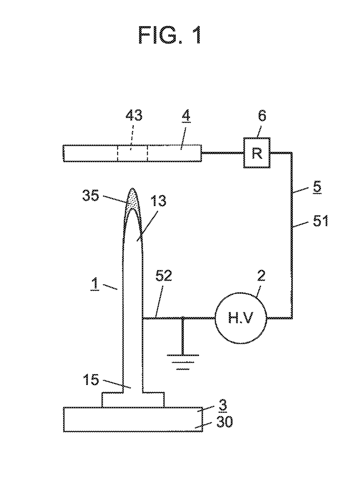
[0046]FIG. 1 illustrates a basic configuration of an electrostatic atomizing device according to a first exemplary embodiment. The electrostatic atomizing device according to the present exemplary embodiment includes discharge electrode 1, voltage applicator 2, liquid supplying unit 3, counter electrode 4, current path 5, and limiting resistor 6.
[0047]Discharge electrode 1 is a long thin electrode having a needle shape. Discharge electrode 1 has front-end portion 13 at one end, in an axial direction, of discharge electrode 1 and has base-end portion 15 at the other end, in the axial direction, of the discharge electrode 1 (on a side opposite to front-end portion 13). The term “needle shape” as used herein encompasses not only a case where a front end is sharply pointed, but also a case where a front end is rounded.
[0048]Voltage applicator 2 is electrically connected to discharge electrode 1 and counter electrode 4 so that a high voltage is applied across discharge electrode 1 and co...
second exemplary embodiment
[0066]An electrostatic atomizing device according to a second exemplary embodiment is described below with reference to FIGS. 4A and 4B. Detailed description of constituent elements that are similar to those in the first exemplary embodiment is omitted.
[0067]FIG. 4A illustrates a basic configuration of an electrostatic atomizing device according to the present exemplary embodiment. The electrostatic atomizing device according to the present exemplary embodiment is different from the electrostatic atomizing device according to the first exemplary embodiment in that counter electrode 4 includes needle-shaped electrode portion 41 and supporting electrode portion 42 that supports needle-shaped electrode portion 41.
[0068]Needle-shaped electrode portion 41 protrudes toward discharge electrode 1 from supporting electrode portion 42. Of all portions of counter electrode 4, a tip of needle-shaped electrode portion 41 is located closest to discharge electrode 1. Needle-shaped electrode portio...
third exemplary embodiment
[0073]An electrostatic atomizing device according to a third exemplary embodiment is described below with reference to FIG. 5. Detailed description of constituent elements that are similar to those in the first exemplary embodiment is omitted.
[0074]In the electrostatic atomizing device according to the present exemplary embodiment, capacitor 7 that adjusts a discharge frequency of leader discharge is disposed in a middle of current path 5. Capacitor 7 is connected in parallel with voltage applicator 2. Since electric current resistance during flow of an instantaneous electric current is very small in leader discharge as described above, the discharge frequency of the leader discharge is effectively adjusted by disposing capacitor 7 on current path 5.
[0075]Capacitor 7 is not limited to one using a dedicated element and can have any configuration as long as capacitor 7 has preset capacitance.
PUM
 Abstract
Description
Claims
Application Information
 - R&D
- Intellectual Property
- Life Sciences
- Materials
- Tech Scout
- Unparalleled Data Quality
- Higher Quality Content
- 60% Fewer Hallucinations
Browse by: Latest US Patents, China's latest patents, Technical Efficacy Thesaurus, Application Domain, Technology Topic, Popular Technical Reports.
© 2025 PatSnap. All rights reserved.Legal|Privacy policy|Modern Slavery Act Transparency Statement|Sitemap|About US| Contact US: help@patsnap.com


