
Slide bearing

Inactive Publication Date: 2018-02-01
TAIHO INDUSTRIES CO LTD
View PDF0 Cites 0 Cited by
  • Summary
  • Abstract
  • Description
  • Claims
  • Application Information

AI Technical Summary

Benefits of technology

The patent describes a design for a friction reduction device that reduces the amount of oil consumed during operation. It achieves this by using a narrow groove that allows for smoother movement and a reduction in the amount of oil needed. Additionally, the device includes projecting and recessed portions that guide lubricant oil to the inner surface of the device, increasing the amount of oil sucked back and reducing the overall amount of oil needed. These design features lead to improved efficiency and reduced oil consumption.

Problems solved by technology

Conventionally known sliding bearings, for supporting a crankshaft of an engine, having a split structure in which two members obtained by splitting a cylindrical member in half are combined are plagued by a large friction due to high viscosity of oil during a cold engine operation.

Method used


Image

  • Slide bearing
  • Slide bearing
  • Slide bearing

Examples


Embodiment Construction

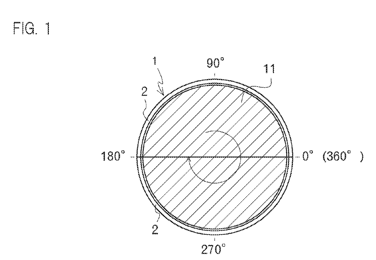
[0019]An embodiment of the invention is described below. FIG. 1 is a front view of a sliding bearing 1, with a vertical direction of the sheet defined as an upper and lower direction, and a direction between a closer side and a farther side of the sheet defined as an axial direction (front and rear direction).

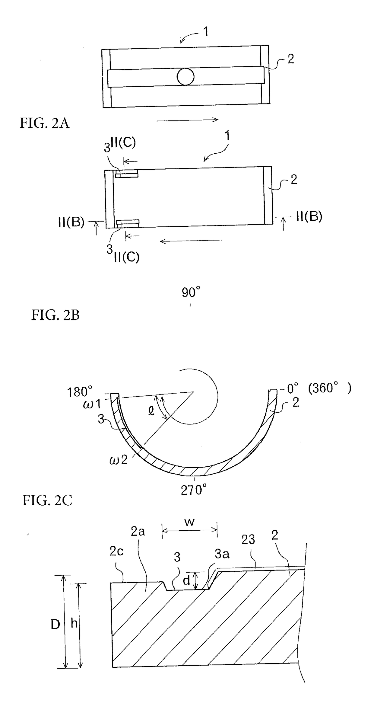
[0020]First of all, half members 2 as parts of the sliding bearing 1 according to an embodiment of the present invention are described with reference to FIG. 1 and FIGS. 2A-2C.

[0021]The sliding bearing 1 is a cylindrical member, and is applied to a sliding bearing structure of a crankshaft 11 of an engine as illustrated in FIG. 1. The sliding bearing 1 includes two half members 2 and 2. The two half members 2 and 2 have shapes obtained by splitting a cylinder in half in a direction parallel with the axial direction, and each have a semicircular cross-sectional shape. In the present embodiment, the half members 2 and 2 are arranged in the upper and lower direction with joining s...


PUM


Abstract

A sliding bearing may include half members, obtained by splitting a cylinder in half, arranged in an upper and lower direction. A narrow groove extending in the circumference direction may be formed on one of the half members, on a downstream side in a rotation direction. A circumference edge portion may be formed on an outer side of the narrow groove, and may be formed to be lower than a contact surface of the sliding bearing to be in contact with a shaft. Projecting portions and recessed portions may be alternately arranged on a bottom surface of the narrow groove in parallel with a longitudinal direction of the narrow groove. A coating layer may be formed on an inner circumference surface of the half member, the coating layer including at least a region from an inner circumference end to an intermediate portion inner-side surface of the narrow groove.

Description

CROSS REFERENCE TO RELATED APPLICATIONS[0001]This is the U.S. national stage of application No. PCT / JP2016 / 055953, filed on Feb. 26, 2016. Priority under 35 U.S.C. §119(a) and 35 U.S.C. §365(b) is claimed from Japanese Application No. 2015-039115, filed on Feb. 27, 2015, the disclosures of which are also incorporated herein by reference.TECHNICAL FIELD[0002]The present invention relates to a technique of a sliding bearing, and can be applied to a sliding bearing including half members, obtained by splitting a cylinder in half in a direction parallel with an axial direction, arranged in an upper and lower direction.BACKGROUND ART[0003]Conventionally known sliding bearings, for supporting a crankshaft of an engine, having a split structure in which two members obtained by splitting a cylindrical member in half are combined are plagued by a large friction due to high viscosity of oil during a cold engine operation. Thus, one known bearing has relief portions (narrow grooves) formed ove...

Claims


Application Information

Patent Timeline
IPC IPC(8): F16C17/02F16C33/10F16C9/02F16C33/08
CPCF16C17/022F16C33/08F16C33/103F16C9/02F16C33/046F16C33/1025F16C33/1065F16C33/122F16C33/14F16C17/02F16C33/10
Inventor SEKI, DAISUKETAKAGI, YUJI
Owner TAIHO INDUSTRIES CO LTD
Features
  • Generate Ideas
  • Intellectual Property
  • Life Sciences
  • Materials
  • Tech Scout
  • Unparalleled Data Quality
  • Higher Quality Content
  • 60% Fewer Hallucinations
Learn More