Trapezoidal rib mounting bracket with flexible legs

a technology of mounting brackets and trapezoids, which is applied in the direction of heat collector mounting/support, sustainable buildings, light and heating equipment, etc., can solve the problems of inability to install structures on standing seam panels in one or more locations, and affecting the safety of users

Active Publication Date: 2018-02-01
RMH TECH LLC
View PDF1 Cites 19 Cited by
  • Summary
  • Abstract
  • Description
  • Claims
  • Application Information

AI Technical Summary

Benefits of technology

[0016]The upper section of the mounting bracket may include multiple sections. A first section for the upper section may include the upper wall and may be of a first width (measured in the lateral or “x” dimension for the mounting bracket). A second section for the upper section may be positioned somewhere below the first section (when the mounting bracket is in an upright position on a horizontal supporting surface), may be of a second width (measured in the lateral or “x” dimension for the mounting bracket) that is larger than the first width, may be defined by a pair of sidewalls that are disposed in parallel relation (that are spaced in the lateral or “x” dimension for the mounting bracket), may have a height (measured in the “y” dimension for the mounting bracket) of at least about 0.75″, or any combination thereof. A receptacle may be located somewhere between the upper wall and the noted second section (in the “y” dimension for the mounting bracket), where this receptacle is at least partially separated from the second section (e.g., by a least one rib offsetting member—discussed below) and accommodates receipt of a nut, bolt head, or the like. Having the noted second section with a height of at least 0.75″ (in the “y” dimension for the mounting bracket) provides a suitable space for wire management (e.g., such that PV module wire, cables or the like may be directed completely through the second section (from one open bracket end to the opposite open bracket end) for the case of a photovoltaic module installation). Such a second section for the upper section may also be used to dispose one or more photovoltaic modules in a desired spacing to an underlying roofing surface.
[0017]The mounting bracket may include at least one rib offsetting member and which may be characterized as being part of a lowermost end of the upper section for the mounting bracket (when disposed in an upright position on a horizontal supporting surface). Such a rib offsetting member(s) may be disposed on an upper rib wall of a trapezoidal rib when the mounting bracket is an installed configuration, for instance to maintain the upper wall of the mounting bracket in spaced relation to such an upper rib wall. Although there could be a small space between the rib offsetting member(s) for the mounting bracket and the upper rib wall in the installed configuration, no other portion of the mounting bracket will be disposed in such a space.

Problems solved by technology

Standing seam panels are expensive compared to other metal panels, and building surfaces defined by metal panels may be more costly than other types of building surface constructions.
Installing structures on standing seam panel building surfaces in a manner that punctures the building surface at one or more locations is undesirable in a number of respects.
Another is that puncturing a metal panel building surface can present leakage and corrosion issues.

Method used


Image

  • Trapezoidal rib mounting bracket with flexible legs
  • Trapezoidal rib mounting bracket with flexible legs
  • Trapezoidal rib mounting bracket with flexible legs

Examples


Embodiment Construction

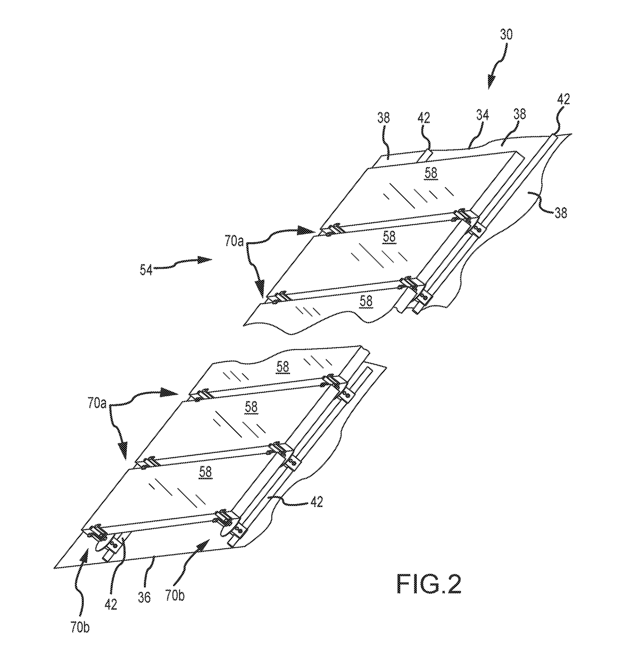
[0132]FIG. 2 illustrates an assembly 30 in the form of a building surface 34, a photovoltaic or solar cell array 54 defined by a plurality of photovoltaic modules or solar cell modules 58 (only schematically shown in FIG. 2), and a plurality of mounting assemblies 70a, 70b. The building surface 34 is defined by interconnecting a plurality of panels 38. Although the panels 38 may be formed from any appropriate material or combination of materials, typically they are in the form of metal panels 38. In any case, each adjacent pair of panels 38 is interconnected in a manner so as to define a standing seam 42 (only schematically shown in FIG. 2). A base 46 is disposed between the opposing edges of each panel 38 (e.g., FIG. 3). The entirety of the base 46 may be flat or planar. However, one or more small structures may be formed / shaped into the base 46 of one or more panels 38 of the building surface 34 to address oil canning. These structures are commonly referred to as crests, minor rib...


PUM


Abstract

A mounting bracket (320) for trapezoidal rib profiles is disclosed. This mounting bracket (320) includes an upper section (330) and a lower section (350). A first leg (352a) in a second leg (352b) extend from a lower portion of the upper section (330) in diverging relation to one another. Each of these legs (352a, 352b) is deflectable through a certain range of motion to accommodate installation of the mounting bracket (320) on a variety of different trapezoidal rib profiles.

Description

CROSS-REFERENCE TO RELATED APPLICATIONS[0001]This patent application claims the benefit of co-pending U.S. Provisional Patent Application Ser. No. 62 / 368,831, entitled “TRAPEZOIDAL RIB MOUNTING BRACKET WITH FLEXIBLE LEGS,” filed on Jul. 29, 2016, and the entire disclosure of which is hereby incorporated by reference.FIELD OF THE INVENTION[0002]The present invention generally relates to installing structures on a building surface and, more particularly, to a mounting bracket for use with trapezoidal rib panels.BACKGROUND[0003]Metal panels are being increasingly used to define building surfaces such as roofs and sidewalls. One type of metal panel is a standing seam panel, where the edges of adjacent standing seam panels of the building surface are interconnected in a manner that defines a standing seam. Standing seam panels are expensive compared to other metal panels, and building surfaces defined by metal panels may be more costly than other types of building surface constructions.[...

Claims


Application Information

Patent Timeline
Patent Type & Authority Applications(United States)
IPC IPC(8): F24J2/52
CPCF24J2/5245F24J2/5258F24S25/615F24S2025/018F24S2025/021F24S25/60Y02B10/20Y02E10/47F24S25/61F24S25/636Y02B10/10Y02E10/50
Inventor HADDOCK, DUSTIN M.M.HADDOCK, ROBERT M.M.HOLLEY, NIKOLAUS J.
Owner RMH TECH LLC
Why Eureka
Try Eureka