Thermal pattern sensor with shared heating elements

a technology of thermal pattern sensor and heating element, applied in the field of thermal pattern sensor, can solve the problems of sensor drawback, level of signal obtained, resolution that can be achieved with these techniques, and incompatible with the resolutions sought for certain thermal pattern sensor

Active Publication Date: 2018-02-01
IDEMIA IDENTITY & SECURITY FRANCE +1
View PDF2 Cites 10 Cited by
  • Summary
  • Abstract
  • Description
  • Claims
  • Application Information

AI Technical Summary

Problems solved by technology

These sensors have the drawback, however, of making a measurement which depends solely upon the temperature difference between the finger and the sensor.
The level of the signal obtained may therefore be zero when the finger and the sensor are at the same temperature (for example when the finger remains on the sensor for a certain time), or the contrast of the detected images m...

Method used


Image

  • Thermal pattern sensor with shared heating elements
  • Thermal pattern sensor with shared heating elements
  • Thermal pattern sensor with shared heating elements

Examples


first embodiment

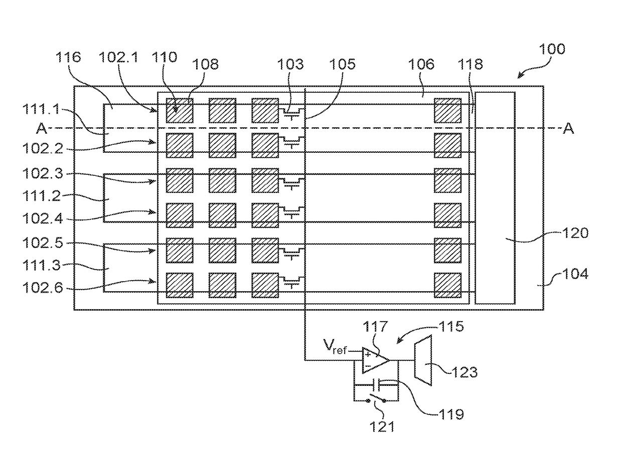
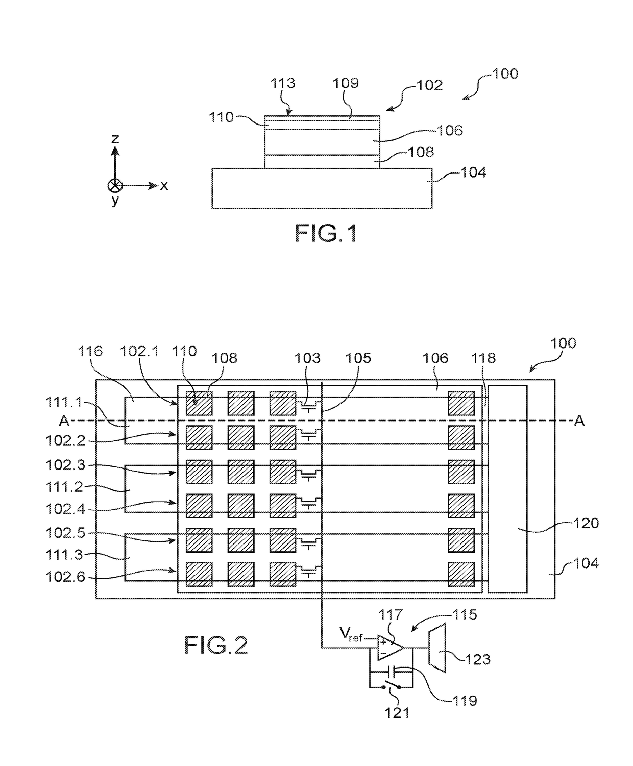
[0017] the thermal pattern sensor may be such that:[0018]each pixel moreover comprises a selection transistor connected to the reading electrode of said pixel,[0019]for each line of pixels, the gates of the selection transistors for said line of pixels are connected to a selection line of said line of pixels,[0020]for each column of pixels, the selection transistors of the pixels of said column of pixels are connected to a reading column of said column of pixels which is connected to a reading circuit common to the pixels of said column of pixels.

[0021]In this case the thermal pattern sensor may moreover comprise a control circuit capable of implementing at least the following steps for reading a line of pixels:[0022]setting the selection transistors of the pixels of said line to an ON state;[0023]application of a heating voltage to the ends of the electrically conductive portion associated with said line of pixels;[0024]re-initialisation of the reading circuits;[0025]waiting during...

second embodiment

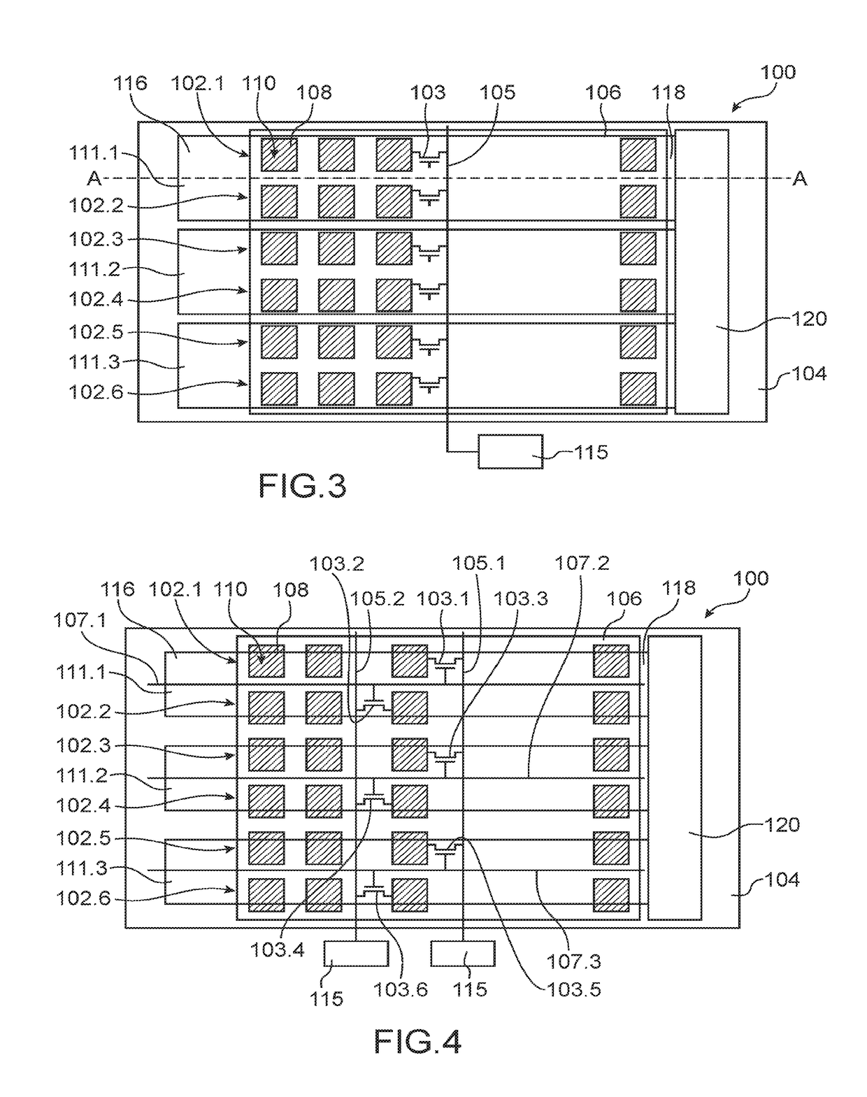
[0032] it is possible for the thermal pattern sensor to be such that:[0033]each pixel moreover comprises at least one selection transistor connected to the reading electrode of said pixel,[0034]the gates of the selection transistors of the pixels belonging to adjacent lines of pixels capable of being heated simultaneously by a given electrically conductive portion are connected to a single common selection line for said lines of pixels,[0035]for each column of pixels, the selection transistors whose gates are connected to the same selection line are connected to different reading columns, each connected to a different reading circuit.

[0036]Compared to the first embodiment, the sensor according to this second embodiment comprises a greater number of reading columns, as well as a greater number of reading circuits. Due to the fact that the lines of pixels heated by a given electrically conductive portion may be read simultaneously, the reading of the pixels is simplified, and there is...

third embodiment

[0142]FIG. 5 shows the sensor 100 according to a

[0143]In comparison with the previous embodiments, and for at least some of the lines of pixels 102 of the sensor 100, each of the reading electrodes 108 of these lines of pixels 102 is not distinct for each of the pixels 102, but is common to two pixels from a given column and which are heated by different portions 111. Thus for two adjacent lines of pixels each of which is associated with a different portion 111, the reading electrodes of two pixels found in a given column are electrically connected together due to the fact that they are formed by the same portion of the electrically conductive material. In the example shown in FIG. 5, the reading electrodes of the pixels of a given column, and which belong to two lines of pixels 102.2 and 102.3, each associated with a different heating element (the heating elements of the line of pixels 102.2 being formed by the portion 111.1 and those of the line of pixels 102.3 being formed by the...


PUM


Abstract

Thermal pattern sensor comprising a matrix of several lines and columns of pixels, each pixel comprising at least one pyroelectric capacitance formed by at least one portion of pyroelectric material arranged between a lower electrode and an upper electrode, wherein a first of the lower and upper electrodes forms an electrode for reading the pixel, and moreover comprising a plurality of electrically conductive portions each capable of Joule effect heating, independently of the other electrically conductive portions, of the portions of pyroelectric material of the pyroelectric capacitances of the pixels of at least two adjacent lines of pixels associated with the electrically conductive portion, and arranged facing at least a part of the surface of the reading electrodes of each of the pixels of the lines associated with the electrically conductive portion.

Description

TECHNICAL FIELD AND PRIOR ART[0001]The invention relates to a thermal pattern sensor wherein the heating elements are shared so that each of the heating elements is capable of heating several lines of pixels. This thermal pattern sensor advantageously corresponds to a fingerprint detector that uses thermal detection.[0002]A fingerprint detector comprises means of thermal detection. These means of thermal detection may correspond to pyroelectric elements, diodes, thermistors or any other temperature-sensitive elements which can convert a temperature variation into an electrical potential or current variation.[0003]Detection of a fingerprint may be performed by so-called “passive” sensors which use temperature differences between the finger and the sensor, as described in documents U.S. Pat. No. 4,394,773, U.S. Pat. No. 4,429,413 and U.S. Pat. No. 6,289,114. These sensors have the drawback, however, of making a measurement which depends solely upon the temperature difference between t...

Claims


Application Information

Patent Timeline
IPC IPC(8): G06K9/00G01R19/10G01R19/32H03K17/94H03K17/96
CPCG06K9/0002H03K17/941G01R19/10G01R19/32H03K17/962G01J5/34G06V40/1306G06V40/1329
Inventor MAINGUET, JEAN-FRANCOISFOURRE, JOEL YANN
Owner IDEMIA IDENTITY & SECURITY FRANCE
Why Eureka
Try Eureka