
OLED display and source driver

a source driver and light-emitting diode technology, applied in the field of display, can solve the problems of increasing the cost of the driver system, and achieve the effects of prolonging the service life of the driver system, and reducing the opening ration

Active Publication Date: 2018-02-01
TCL CHINA STAR OPTOELECTRONICS TECH CO LTD
View PDF8 Cites 5 Cited by
  • Summary
  • Abstract
  • Description
  • Claims
  • Application Information

AI Technical Summary

Benefits of technology

The present invention provides an OLED display and a source driver that can select different output channels for data signals. This results in alternating display of different pixels, which shortens the light-emitting time of OLED and slows down the ageing of the display. Compared to the known techniques, the invention achieves this without changes in pixel structure or reducing opening ratio. The source driver uses an odd-even channel selection module to switch between high and low output channels, allowing for alternating display of odd-numbered and even-numbered pixel units. This results in a normal display with delayed ageing of the OLED display.

Problems solved by technology

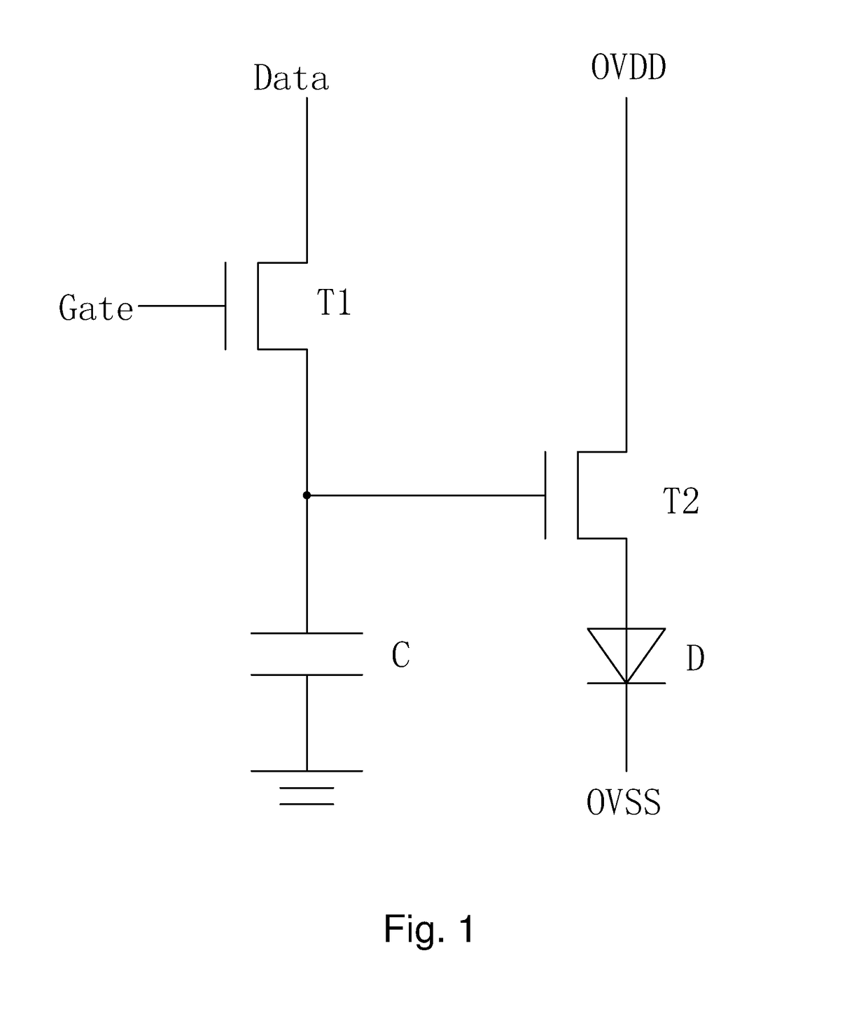
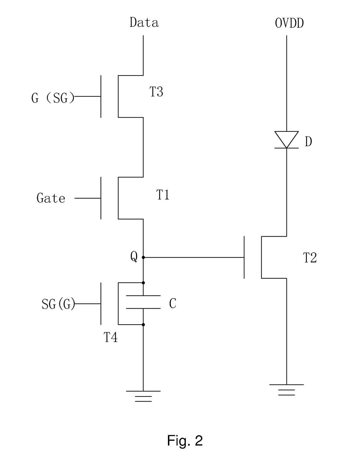
However, the above improvement adds two TFTs, which leads to a smaller opening ratio of the OLED display, as well as two control signals, which increases the cost for the driver system.

Method used


Image

  • OLED display and source driver
  • OLED display and source driver
  • OLED display and source driver

Examples


first embodiment

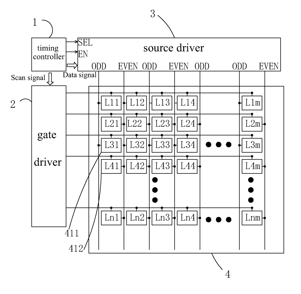
[0037]Optionally, referring to FIG. 4, in the OLED display, the adjacent pixel units in all four direction (i.e., above, below, left and right) to each odd-number pixel unit 411 are all even-numbered pixel units 412. The odd-numbered pixel units 411 of the same row of pixel units are connected through a data line disposed at a side of the row of pixel units to an odd-number output channel ODD; the even-numbered pixel units 412 of the same row of pixel units are connected through a data line disposed at the other side of the row of pixel units to an even-number output channel EVEN.

second embodiment

[0038]Optionally, referring to FIG. 5, in the OLED display, the pixel units of an odd-numbered row of pixel units are all odd-numbered pixel units 411, the pixel units of an even-numbered row of pixel units are all even-numbered pixel units 412, each pixel unit of odd-numbered row is connected through a data line to an odd-number output channel ODD, and each pixel unit of even-numbered row is connected through a data line to an even-number output channel EVEN.

[0039]Refer to FIGS. 4, 6, 7, or FIGS. 5, 6, 7. The timing controller 1 provides a strobe enabling signal EN and an odd-even selection signal SEL, the odd-even channel selection module 33 controls the logic circuit and driver module 31 to select strobe only odd-numbered output channels ODD, strobe only even-numbered output channels EVEN, or strobe both odd-numbered ODD and even-numbered EVEN output channels. The logic circuit and driver module 31 outputs data signals to corresponding pixel units in accordance with the output ch...


PUM


Abstract

The invention provides an OLED display and a source driver. The output channels of source driver are divided into odd-numbered (ODD) and even-numbered (EVEN) output channels. With the odd-even channel selection module (33) in source driver to control the logic circuit and driver module (31) to select only odd-numbered (ODD), only even-numbered (EVEN) output channels or both for output based on strobe enabling signal (EN) and odd-even selection signal (SEL). Moreover, through rapid switching between high and low of the odd-even selection signal (SEL), the switching of outputting to only odd-numbered (ODD) and only even-numbered (EVEN) output channels is achieved so that odd-numbered pixel units and even-numbered pixel units in OLED display emit light alternatingly. Without changing pixel structure and reducing opening ration, while ensuring normal display, the invention shortens the light-emitting time of OLED inside each pixel to delay OLED display ageing.

Description

BACKGROUND OF THE INVENTION1. Field of the Invention[0001]The present invention relates to the field of display, and in particular to an organic light emitting diode (OLED) display and a source driver.2. The Related Arts[0002]The organic light-emitting diode (OLED) display has the advantages of active light-emitting, low driving voltage, high light-emitting efficiency, short response time, high clarity and high contrast, near 180°, wide operation temperature range, and the ability to realize flexible display and large-size full-color display, and is often considered as the technology with most potential.[0003]The OLED usually comprises: an anode, an organic light-emitting layer disposed at the anode, an electron transmission layer disposed at the organic light-emitting layer, and a cathode disposed at the electron transmission layer. The known OLED is mostly driven by direct current (DC), and emitting the hole from the anode and electron from the cathode to the organic light-emittin...

Claims


Application Information

Patent Timeline
Patent Type & Authority Applications(United States)
IPC IPC(8): G09G3/3291H01L51/52H01L27/32G09G3/3225
CPCG09G3/3291G09G3/3225H01L51/5203H01L27/3262G09G3/3275G09G3/3233G09G2310/0254G09G2320/043H10K59/1213H10K50/805
Inventor FU, JIANHANGHWANG, TAIJIUN
Owner TCL CHINA STAR OPTOELECTRONICS TECH CO LTD
Learn More