

Vehicle charging lanes
a charging lanes and vehicle technology, applied in the direction of navigation instruments, battery/fuel cell control arrangements, instruments, etc., can solve the problems of associated charging stations, energy loss through heat, and power was
Active Publication Date: 2018-02-08
HERE GLOBAL BV
View PDF12 Cites 45 Cited by
- Summary
- Abstract
- Description
- Claims
- Application Information
AI Technical Summary
Benefits of technology
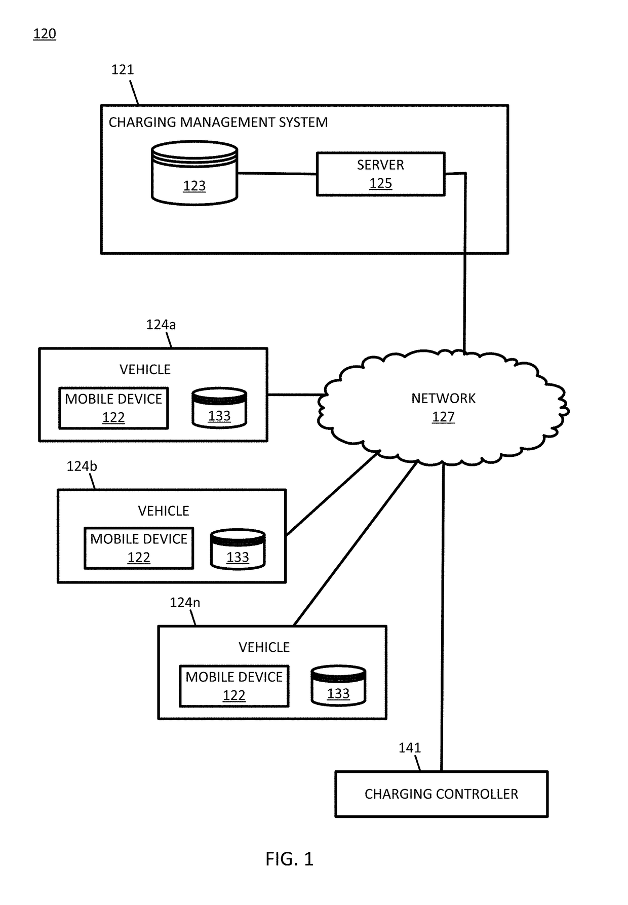
The patent describes a system and method for implementing lane charging for a roadway. The system includes a geographic database with data about road segments in a specific region, a communication interface for receiving real-time data, and a lane charging management device. The lane charging management device generates a charging command for a charging device associated with a road segment based on the real-time data. This allows for more efficient and accurate charging of electric vehicles in specific lanes on specific roads.
Problems solved by technology
The toll may be associated with the infrastructure or the ongoing operational requirements or costs for the charging lanes.
In addition, when charging lanes go unused, or used minimally, power is wasted.
Even when inductive charging units are not charging electric vehicles, energy is lost through heat.
For example, when many vehicles are headed for a particular road segment, or currently traveling on the road segment, the associated charging stations 181 may be overloaded and / or traffic congestion may be present on the road segment.
For example, the battery level may not be low enough for the vehicle to seek out additional charge otherwise.
For example, the battery level may not be low enough for the vehicle to seek out additional charge otherwise.
The amount of batteries may exceed the electrical drive propulsion needs of the electric truck.
Additionally, the illustrations are merely representational and may not be drawn to scale.
Method used
View moreImage
Smart ImageViewing Examples

Examples
embodiment 1
[0156]A method for implementing lane charging for a roadway, the method comprising:[0157]identifying a road segment in a geographic region;[0158]receiving real time data at a lane charging management device; and[0159]generating a lane charging command for a charging device associated with the road segment in response to the real time data.
embodiment 2
[0160]The method of embodiment 1, wherein the real time data includes a route for a vehicle.
embodiment 3
[0161]The method of embodiments 1-2, wherein the lane charging command is based on an attribute associated with the road segment.
Login to View More PUM
 Abstract
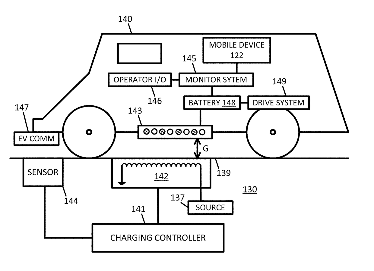
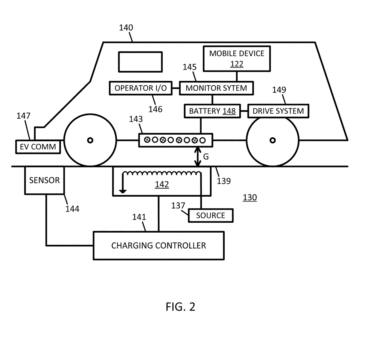
Embodiments include apparatus and methods for implementing lane charging for a roadway. A road segment in a geographic region is identified from a geographic database. The road segment may be identified based on the geographic position of a vehicle. A lane charging management device receives real time data related to the vehicle, the environment, or the electricity associated with the charging station. A lane charging command for a charging device associated with the road segment is generated in response to the real time data.
Description
FIELD[0001]The following disclosure relates to control of one or more charging lanes for charging an electric vehicle and / or control of one or more electric vehicles or an associated device with respect to the one or more charging lanes.BACKGROUND[0002]An electric vehicle is a vehicle that includes an electric propulsion system. The electric propulsion system may include an electric motor and a battery. Hybrid vehicles may also include a combustion engine as well as a regenerative power system that transfers excess power from the combustion engine to the electric propulsion system.[0003]Electric vehicles may be charged by a charging station. The charging systems may be placed in parking garages, parking lots, or consumer homes. The electric vehicle may be electrically coupled to the charging station using a cord. Depending on the electrical input to the charging system, which may vary in amplitude and in number of phases, different charging stations may be capable of charging the el...
Claims
Login to View More Application Information
Patent Timeline
 IPC IPC(8): B60M3/04B60L11/18B60L5/00
CPCB60M3/04B60L5/005B60L11/1801B60L2240/66B60L11/1861B60L2240/62B60L11/182B60L5/38B60L2240/642B60L2240/665B60L2240/667B60L2240/68Y02T90/16Y02T90/14Y04S10/126B60L50/53B60L53/12B60L55/00B60L53/63B60L58/12B60L53/51B60L53/52Y02E60/00Y02T10/70Y02T10/7072Y02T10/72Y02T90/12G01C21/3415G01C21/3469Y04S30/14B60L53/305B60L53/665B60L53/65B60L2240/622B60L2240/72B60L2240/80B60L2250/16B60L2260/52Y02T90/167G08G1/0968G01C21/34G01C21/00G05D1/00
InventorNELSON, SCOTT DAVID
OwnerHERE GLOBAL BV