Device for Spraying Pressurized Material

a technology of aerosol and spraying nozzle, which is applied in the direction of packaging, transportation and packaging, coatings, etc., can solve the problems of inconvenience, inconvenience, and inconvenience of use, and achieve the effect of improving the orientation of the polyurethane composition jet, facilitating the replacement of the spraying nozzle, and increasing the width

Inactive Publication Date: 2018-02-15
DRAGAN KONSTANTIN MARATOVICH +1
View PDF15 Cites 4 Cited by
  • Summary
  • Abstract
  • Description
  • Claims
  • Application Information

AI Technical Summary

Benefits of technology

[0022]The technical effect of the invention, which can be objectively seen after its implementation, is: an improved and simplified process of joining the spraying nozzle and a spray gun, easier replacement of a spraying nozzle for a spray gun for a shorter time period in case when it is damaged or fails during labor-consuming and long construction works, reducing a possibility of damaging the spraying nozzle outlet when it is attached to a spray gun while using a hard surface as an abutment, an increase in an area of sections of a surface to be treated, and improved orientation of a polyurethane composition jet in space for the purpose of applying it uniformly onto a treated surface, improved separation of a pressurized gas, and prevention of removal of high-boiling hydrocarbon foaming agents which facilitate future polymerization and foaming of a product applied onto a treated surface.
[0023]This technical effect solving the stated task is achieved due to that the spraying nozzle of a spray gun intended for controlled aerosol spraying of a pressurized polyurethane material comprises a cylindrical body which first end is provided with a base having a mounting aperture extending into the cylindrical body and forming a cavity therein for arranging a head of a gun to be attached to a container with an aerosol composition, which base is made in the form of leaves oppositely situated in the same plane and having a size suitable for resting user's fingers when the head of the gun is introduced into the cavity; the other end of the cylindrical body is provided with a cylindrical shoulder having a diameter that is less than a diameter of the body, the cylindrical body having a through bore made therein, which, at a region where a sprayed material exits the container, communicates with a through V-shaped and laterally non-closed recess which width is increased toward an outlet for the sprayed material; oppositely arranged plate-like protrusions adjoin a lateral surface of the cylindrical shoulder, a height of said protrusions being greater than a height of the cylindrical shoulder, and cuts extending to the other end of the cylindrical body are made in outer lateral sides of said protrusions; a wall of said other end has a thickness ensuring that a length of the through bore made in the cylindrical shoulder is greater than the height of the cylindrical shoulder; an end of the mounting aperture adjoining the base has a circumferential cut, and the leaves of the base are provided with an anti-skid finish; and the spraying nozzle is further provided with an attachment means used when in inoperative position.
[0024]Preferably, the attachment means for attaching to an aerosol container is designed so that the spraying nozzle in a plan view thereof has the shape of a staple or similar thereto.
[0025]According to a particular embodiment of the invention, the attachment means is made as a rod which end face is provided with an arrow-like tip, and a stop made as a crossbar is provided opposite to the arrow-like tip and perpendicular to the rod.
[0026]The spraying nozzle of a spray gun for controlled aerosol spraying of a pressurized material according to the invention is made as a single piece in a form of a cylindrical body having a base with a mounting aperture on its first end. The base is made as leaves with an antiskid finish arranged oppositely in the same plane and extending beyond the cylindrical body; a size of the leaves is suitable for resting user's fingers while the head of the spray gun is introduced into the nozzle cavity. This structural embodiment provides a reliable support for the user's fingers and allows their comfortable contact with a surface of the leaves, thus creating a convenient rest enabling to attach the spraying nozzle to the head of the spray gun quickly and easily prior to operation or during it when it is necessary to replace one spraying nozzle with a new one without interrupting the operation process for a long time; and the antiskid finish ensures additional stability for the user's fingers in cases when the user can sweat during a labor-consuming work of applying an aerosol composition onto a surface.
[0027]The base of the spraying nozzle is provided with a mounting aperture extending into the cylindrical body and forming a cavity there, said cavity being used for accommodation of the head of the spray gun. Dimensions of the cavity are selected so as to ensure reliable and quick attachment and detachment of the head of the spray gun; which is subsequently attached to a container, in particular an aerosol container comprising a polyurethane composition.

Problems solved by technology

When operating this apparatus for spraying [1], users may experience difficulties in joining it with the head of the spray gun, since the apparatus body does not comprise any means that may function as a stop for the user's fingers, thus preventing their sliding along the body, which delays the process of joining the apparatus and carrying out corresponding mounting operations.
So, this apparatus cannot ensure comfort in use either during preliminary manipulations therewith or during applying a sprayed composition relative to a surface.
This is provided by the fact that a length of circumference of a protrusion made in one end portion of the nozzle is less than a length of circumference of the nozzle cylindrical body, therefore, a shoulder is formed therebetween which may be used as a stop for the user's fingers in order to prevent them from sliding during attachment of the nozzle [2] to the head of the spray gun; but a width of this shoulder does not enable resting user's fingers thereon comfortably, which may negatively affect comfort and a time period spent for preliminary manipulations with the nozzle [2] as well as for its replacement when it is damaged or fails.
Alternatively, this nozzle [2] may be attached to the head of the spray gun by abutting it against a surface; however, in such a case its outlet V-shaped aperture will be damaged since is does not have any protective means and will directly contact a surface selected for abutment.
In addition, the nozzle [2], similarly to the spraying apparatus [1], does not comprise a means for attaching it to an aerosol container or a spray gun, which would facilitate and accelerate the user's actions in replacing the nozzle [2] during labor-consuming and long construction works.
This ledge also cannot be a reliable abutment for the user's fingers when the nozzle [3] is connected to the head of the spray gun since its width is insufficient for ensuring a reliable abutment for the user's fingers.
Furthermore, the paint spraying nozzle assembly [3], similarly to the known solutions [1] and [2], is not provided with a device that may temporarily retain it in close proximity to a user, e.g., on an aerosol container or on a spray gun itself, which would enable the user to join the nozzle [3] before operation or replace it during the operation, for example in a case it is damaged or fully collapsed.
Finally, it may be stated that the known nozzle [3] has a rather complex configuration, not in a form of a single piece, which, in the long run, would result in increase of a time period required for manufacturing it and in a higher cost of this article.

Method used


Image

  • Device for Spraying Pressurized Material
  • Device for Spraying Pressurized Material
  • Device for Spraying Pressurized Material

Examples


Embodiment Construction

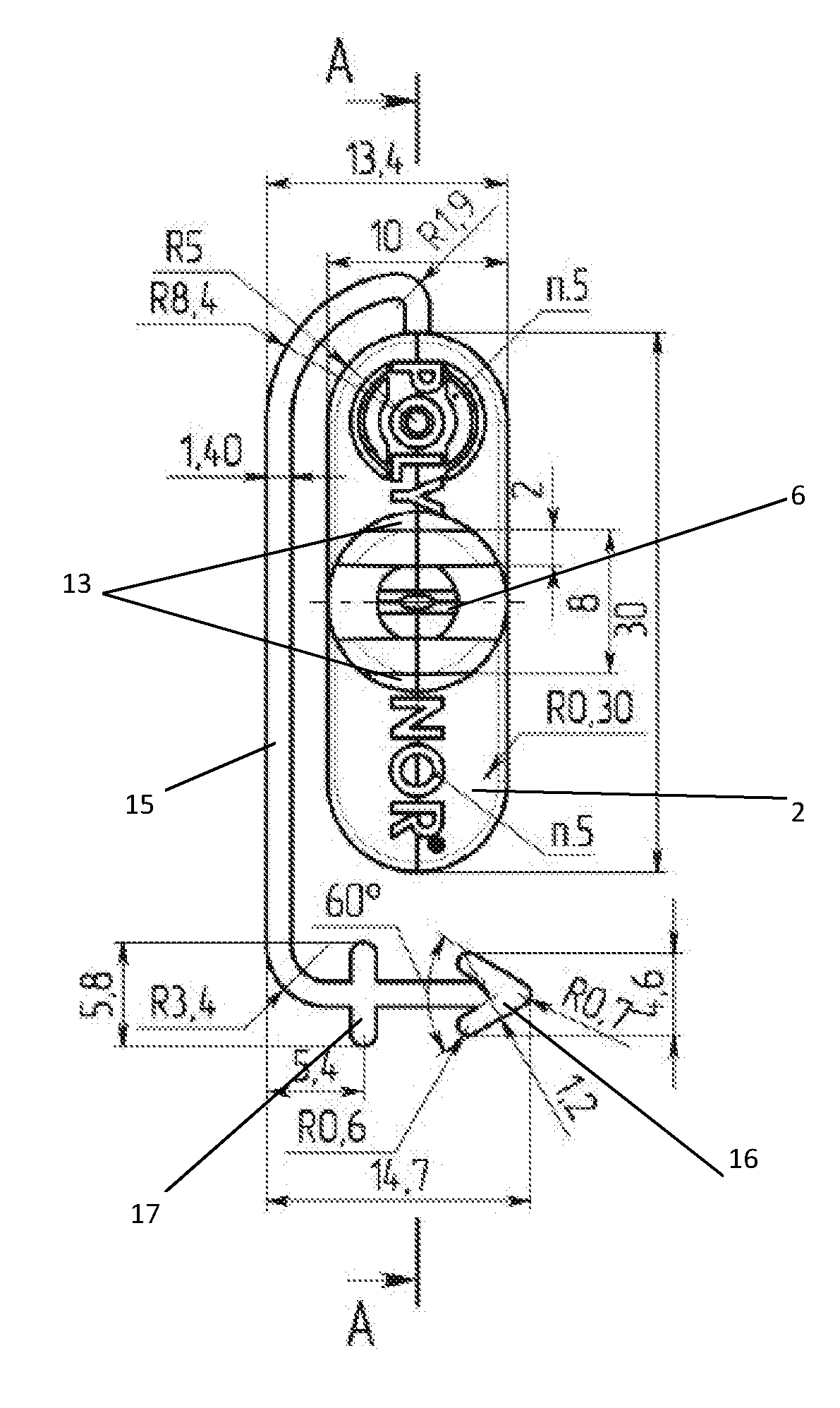
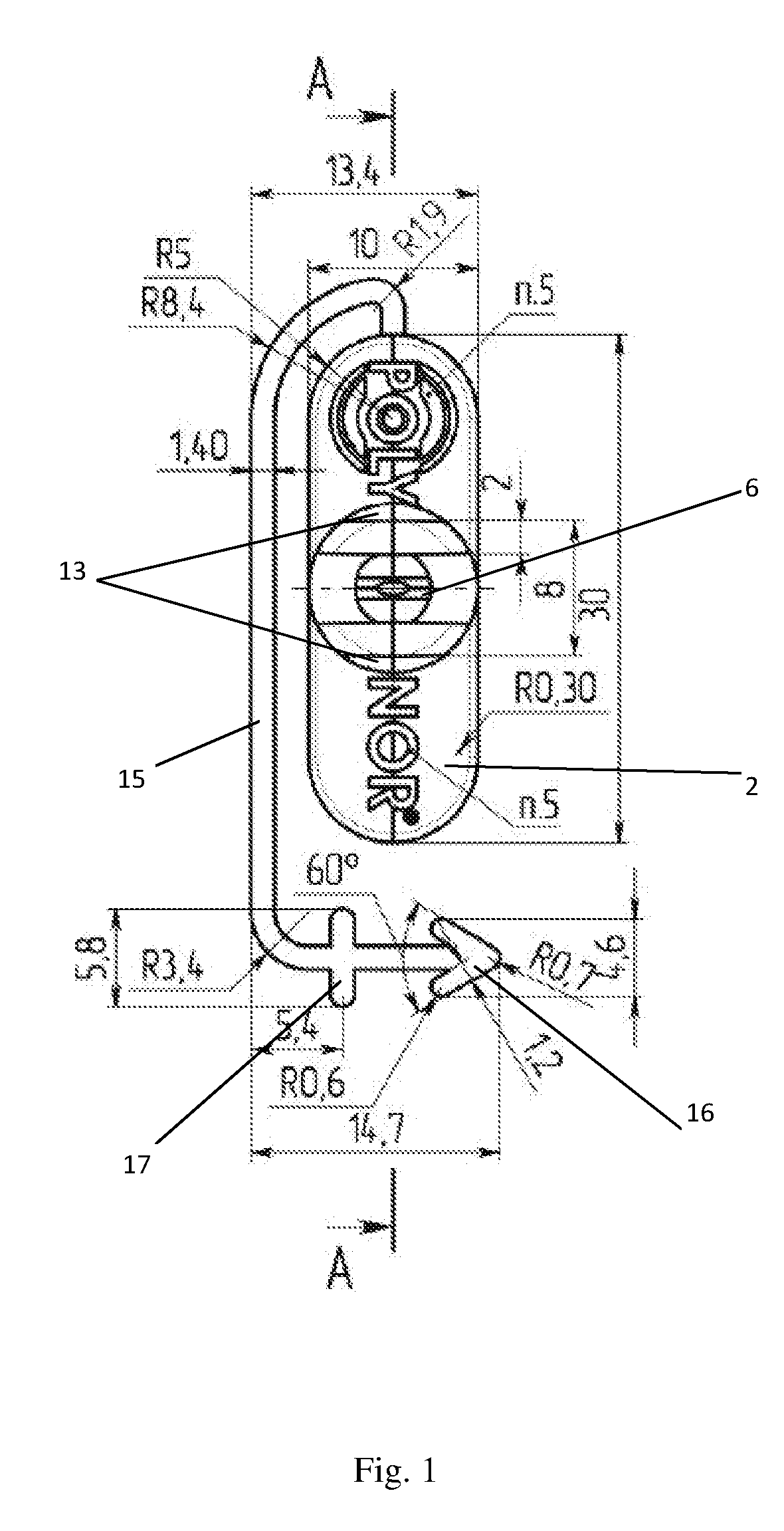
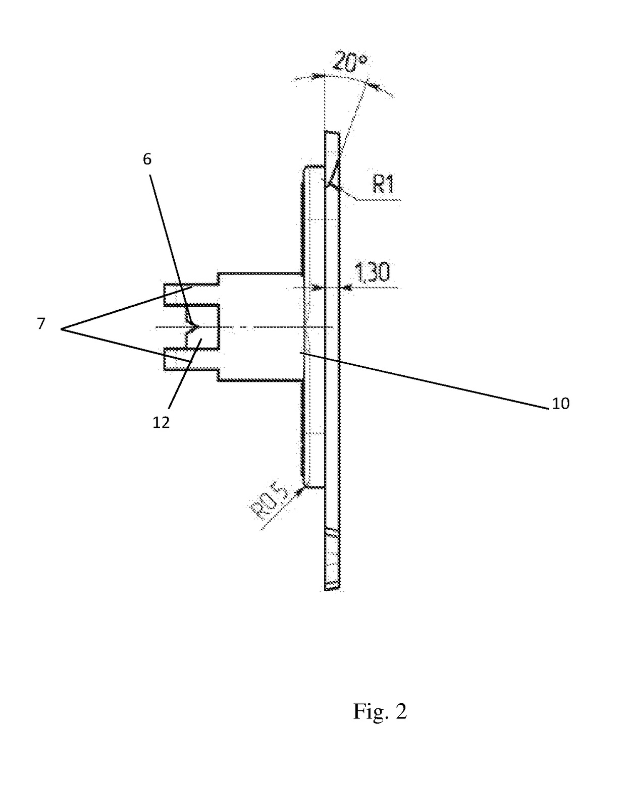
[0037]The claimed invention is explained below by a specific exemplary embodiment which, nevertheless, does not preclude other embodiments, but clearly demonstrates that the totality of the essential features can achieve the stated technical effect solving the task of the invention.

[0038]The spraying nozzle comprises:[0039]a cylindrical body 1;[0040]a base 2;[0041]a mounting aperture 3;[0042]a cavity 4 in the cylindrical body 4;[0043]a through bore 5 in a cylindrical shoulder;[0044]a V-shaped recess 6;[0045]plate-like protrusions 7;[0046]oppositely arranged leaves 8 and 9 forming the base;[0047]a first end 10 of the body;[0048]a second end 11 of the body;[0049]a cylindrical shoulder 12;[0050]cuts 13 on the plate-like protrusions;[0051]an antiskid finish 14;[0052]an attachment means 15;[0053]a tip 16 of the attachment means;[0054]a stop 17 in a form of a crossbar;[0055]a circumferential cut 18 on the mounting aperture.

[0056]The claimed spraying nozzle of a spray gun intended for cont...


PUM


Abstract

Spraying heads may be used in spray guns for applying a pressurized aerosol material in the form of jets or spray. A spraying nozzle for spraying a polyurethane material includes a cylindrical body provided, on a first end, with a base having a mounting aperture extending into the cylindrical body, forming a cavity for arranging a head of a gun. The base of the nozzle is in the form of oppositely-disposed leaves. A second end of the body is provided with a cylindrical shoulder, a through-bore of which is communicated with a V-shaped and laterally non-closed recess at the region of an outlet of the sprayed material. Oppositely arranged plate-like protrusions adjoin a lateral surfaces of the cylindrical shoulder. A mounting aperture end which adjoins the base has a circumferential cut. The spraying nozzle is provided with an attachment means used when in an inoperative position.

Description

FIELD OF THE INVENTION[0001]The present invention relates to a device for spraying an aerosol material by gas pressure applied from within, more particularly to a spraying nozzle used in spray guns for applying a pressurized aerosol material in the form of a jet and / or spray onto various surfaces.PRIOR ART[0002]An apparatus for spraying an aerosol material from a spray gun is known in the art (see: CA1219177, B05B1 / 04, Mar. 17, 1987 [1]).[0003]This apparatus for controlled spraying of a pressurized aerosol material [1] from a spray gun comprises a cylindrical body provided with a mounting aperture extending into the cylindrical body and forming a cavity for arranging a head of the spray gun therein, which gun may be attached to a container comprising an aerosol composition; a V-shaped recess is provided in one end portion of the body, which recess is in communication with a through aperture (cavity) designed for arranging the head of the spray gun, the width of this recess increases...

Claims


Application Information

Patent Timeline
Patent Type & Authority Applications(United States)
IPC IPC(8): B05B1/00B05D1/02B05B5/03B05B1/34
CPCB05B1/005B05B1/3436B05D1/025B05B5/032B05B7/061E04F21/02B05B1/042B05B15/16B05B15/65B65D83/753B05B1/00B65D83/752
Inventor TITOROV, VITALY IVANOVICHDRAGAN, KONSTANTIN MARATOVICH
Owner DRAGAN KONSTANTIN MARATOVICH
Why Eureka
Try Eureka