
Mobile vehicle charging system

a mobile vehicle and charging system technology, applied in the field of charging systems, can solve the problems of increasing the weight of the uav, the inconvenient way of re-supplying electricity for the operator, and the bottleneck of the endurance of the uav, so as to enhance the surveillance effect of the mobile vehicle, increase the cost or space, and improve the surveillance effect. or widespread

Active Publication Date: 2018-02-15
AMKO SOLARA LIGHTING
View PDF2 Cites 13 Cited by
  • Summary
  • Abstract
  • Description
  • Claims
  • Application Information

AI Technical Summary

Benefits of technology

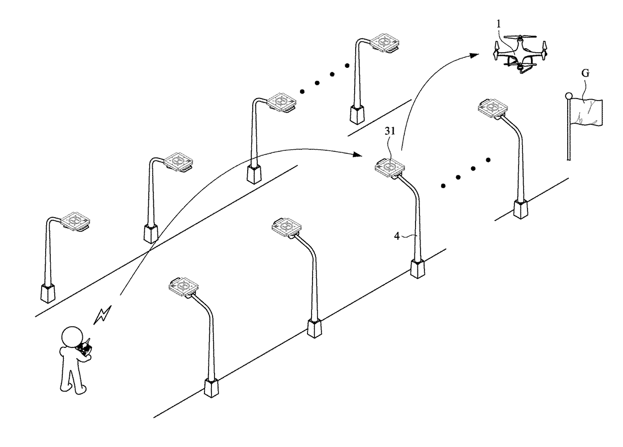
The present invention is a mobile vehicle charging system that can be easily identified and billed for service. The system includes a docking platform with a guidance module for smooth parking of the mobile vehicle. The system also includes multiple camera modules on the docking platform for viewing the mobile vehicle from different angles, improving surveillance along its movement path. Additionally, the invention includes multiple docking platforms on existing street lamps, allowing for quick deployment without additional expense or space. These technical effects enhance the industrial applicability of the mobile vehicle charging system.

Problems solved by technology

For an extended flying distance, a bigger and heavier fuel tank or battery is required, inevitably increasing the weight of the UAV.
Especially, for UAVs using lithium battery, this is a bottleneck for the endurance of these UAVs.
This way of re-supply electricity is rather inconvenient for the operator since manual operation is involved, and the mobile vehicle cannot be charged remotely.
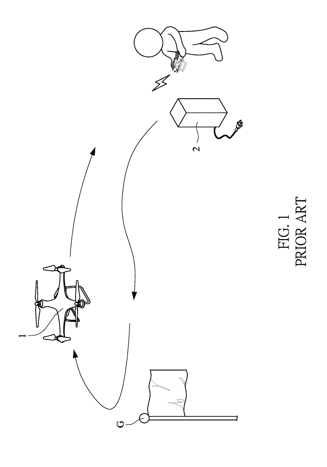
In addition, due to the limitation resulted from electricity supply, the mobile vehicle 1 can only be operated (for example, for aerial photographing) for a short period of time and within a short distance to a target location G. The mobile vehicle 1 with such short endurance therefore is not competent for disaster relief or exploration.
Even though the mobile vehicle 1 is indeed put to these tasks, the efficiency of disaster relief and exploration is severely compromised as the mobile vehicle 1 has to be recharged constantly.
However this solution still has its drawbacks, and there may be budget issue if multiple charging devices is to be installed and staffed.
Space also may not be available, especially for modern developed cities.
As described above, in order to supply mobile vehicle 1's electricity, conventionally the mobile vehicle 1 has to be recharged or its battery has to be replaced, both repeatedly and manually, which is very inconvenient.
Therefore, a major issue for the mobile vehicles is to design a charging system with simplified supply of electricity while resolving the problems of budget limitation and space availability.

Method used


Image

  • Mobile vehicle charging system
  • Mobile vehicle charging system
  • Mobile vehicle charging system

Examples


Embodiment Construction

[0023]The following descriptions are exemplary embodiments only, and are not intended to limit the scope, applicability or configuration of the invention in any way. Rather, the following description provides a convenient illustration for implementing exemplary embodiments of the invention. Various changes to the described embodiments may be made in the function and arrangement of the elements described without departing from the scope of the invention as set forth in the appended claims.

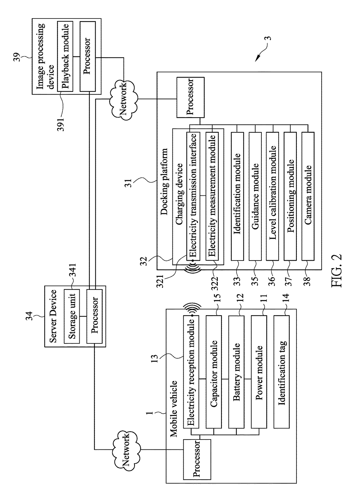
[0024]As shown in FIG. 2, a mobile vehicle charging system 3 according to an embodiment of the present invention is applied to a mobile vehicle 1 which may be an electrical bike, an electrical car, an electrical vessel, or an unmanned aerial vehicle (UAV, or drone). The mobile vehicle 1 includes a power module 11, a battery module 12, and an electricity reception interface 13. The mobile vehicle 1 is moved (such as an electrical car's driving or an UAV's flying) by the power module 11. The battery m...


PUM


Abstract

The mobile vehicle charging system is applied to a mobile vehicle and includes a docking platform and a charging device. The docking platform provides parking to the mobile vehicle. The charging device includes an electricity transmission interface and an electricity measurement module. When the mobile vehicle is parked on the docking platform, the electricity transmission interface charges a battery module through an electricity reception interface of the mobile vehicle. As such, when an operator of the mobile vehicle parks the mobile vehicle onto the docking platform, the mobile vehicle can be automatically charged by the mobile vehicle charging system.

Description

BACKGROUND OF THE INVENTION(a) Technical Field of the Invention[0001]The present invention is generally related to charging systems, and more particular to a charging system for a motor vehicle.(b) Description of the Prior Art[0002]An unmanned aerial vehicle (UAV) has to carry a fuel tank or battery as power source. For an extended flying distance, a bigger and heavier fuel tank or battery is required, inevitably increasing the weight of the UAV. Especially, for UAVs using lithium battery, this is a bottleneck for the endurance of these UAVs.[0003]FIG. 1 is a schematic diagram showing a scenario of a mobile vehicle charged by a conventional charging device. As illustrated, when the mobile vehicle 1 is operated, its electricity is gradually depleted. As the electricity of the mobile vehicle 1 is nearly fully depleted, an operator of the mobile vehicle 1 would recall the mobile vehicle 1, manually connect the mobile vehicle 1 to a charging device 2 so as to charge the mobile vehicle 1...

Claims


Application Information

Patent Timeline
IPC IPC(8): B60L11/18
CPCB60L11/182B64C2201/042B64C39/024B60L53/39B60L53/12Y02T10/70Y02T10/7072Y02T90/14B64U50/34B64U70/30B64U2201/20B64U70/90
Inventor NG, MICHAEL
Owner AMKO SOLARA LIGHTING
Learn More