

Mobile vehicle charging system
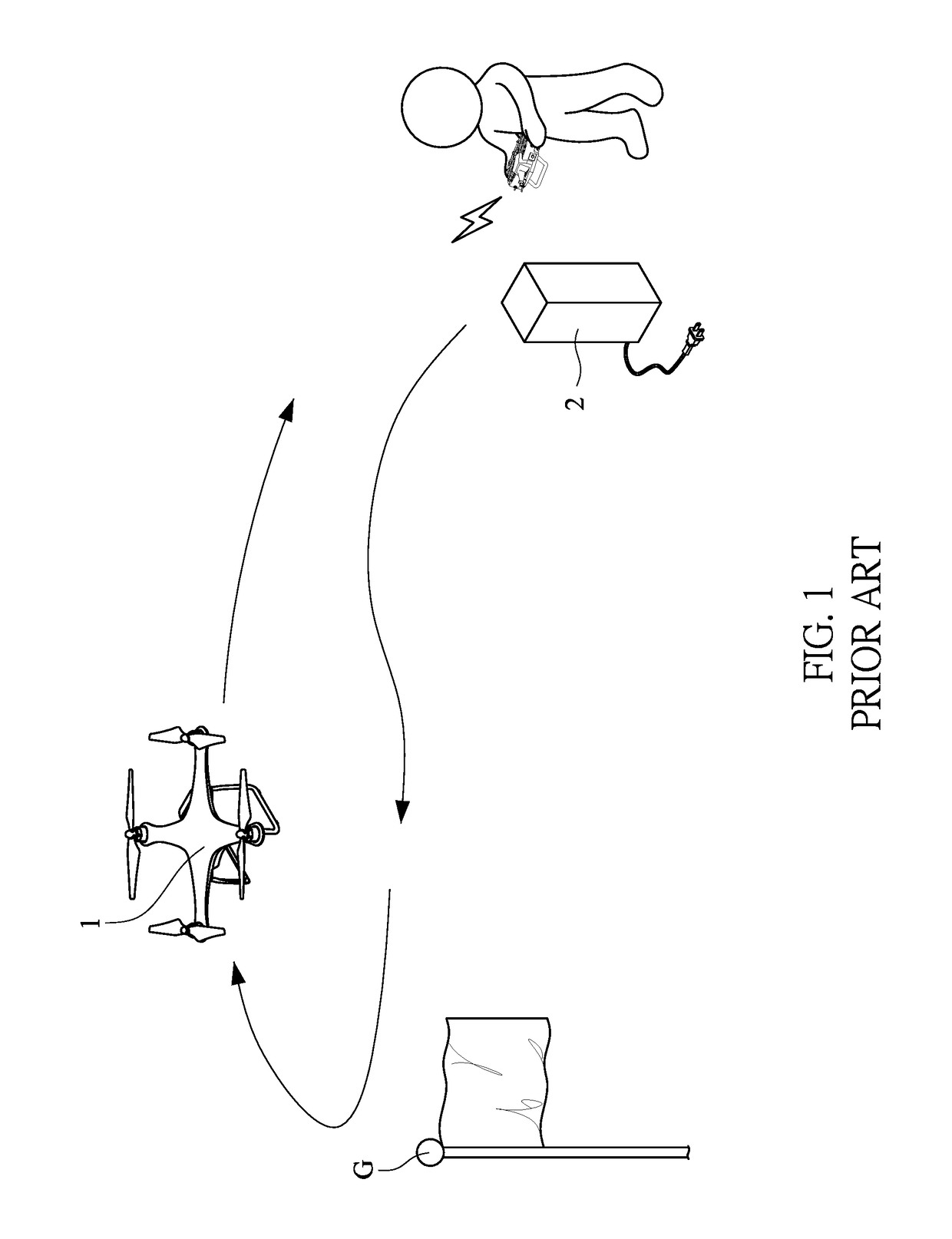
a mobile vehicle and charging system technology, applied in the field of charging systems, can solve the problems of increasing the weight of the uav, the inconvenient way of re-supplying electricity for the operator, and the bottleneck of the endurance of the uav, so as to enhance the surveillance effect of the mobile vehicle, increase the cost or space, and improve the surveillance effect. or widespread
- Summary
- Abstract
- Description
- Claims
- Application Information
AI Technical Summary
Benefits of technology
Problems solved by technology
Method used
Image


Examples
Embodiment Construction
[0023]The following descriptions are exemplary embodiments only, and are not intended to limit the scope, applicability or configuration of the invention in any way. Rather, the following description provides a convenient illustration for implementing exemplary embodiments of the invention. Various changes to the described embodiments may be made in the function and arrangement of the elements described without departing from the scope of the invention as set forth in the appended claims.
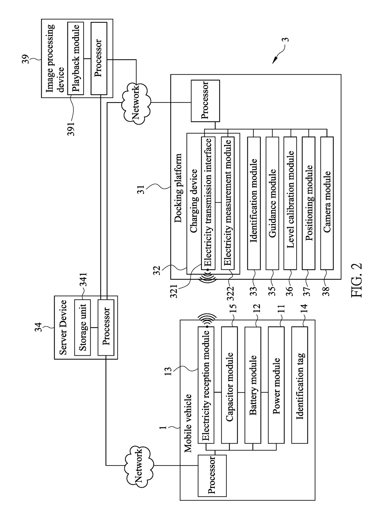
[0024]As shown in FIG. 2, a mobile vehicle charging system 3 according to an embodiment of the present invention is applied to a mobile vehicle 1 which may be an electrical bike, an electrical car, an electrical vessel, or an unmanned aerial vehicle (UAV, or drone). The mobile vehicle 1 includes a power module 11, a battery module 12, and an electricity reception interface 13. The mobile vehicle 1 is moved (such as an electrical car's driving or an UAV's flying) by the power module 11. The battery m...
PUM
 Abstract
Description
Claims
Application Information