
Shift Controller for Vehicle

a technology for shifting controllers and vehicles, applied in the direction of gearing control, control devices, gearing elements, etc., can solve the problem that the reference position of actuators cannot be determined with high accuracy, and achieve the effect of preventing a decrease in responsiveness

Active Publication Date: 2018-02-15
TOYOTA JIDOSHA KK +1
View PDF0 Cites 5 Cited by
  • Summary
  • Abstract
  • Description
  • Claims
  • Application Information

AI Technical Summary

Benefits of technology

The present invention provides a shift controller for a vehicle that prevents a decrease in accuracy of setting a reference position of an actuator due to a decrease in drive voltage of the actuator during reference position setting control. This ensures that the actuator operates with high accuracy and prevents inaccurate shift position switching control. The shift controller also prevents a decrease in responsiveness to a start request from a driver or the like, by not accepting shift position switching requests when the actuator is not outputting the required torque. Additionally, the shift controller prevents the need for repetitive control of setting the reference position by setting the reference position only when the difference between the count value at the start of rotation and the count value in a state without variation is equal to or less than a predetermined value. This ensures that the reference position is set with high accuracy and prevents inaccurate shift position switching control.

Problems solved by technology

Accordingly, in the reference position setting control, there is a likelihood that the reference position of the actuator will not be determined with high accuracy due to a variation in rotational position of the actuator when the rotation of the actuator is restricted by the rotation restricting element.

Method used


Image

  • Shift Controller for Vehicle
  • Shift Controller for Vehicle
  • Shift Controller for Vehicle

Examples


Embodiment Construction

[0033]Hereinafter, a shift controller for a vehicle according to an embodiment of the present disclosure will be described in detail with reference to the accompanying drawings.

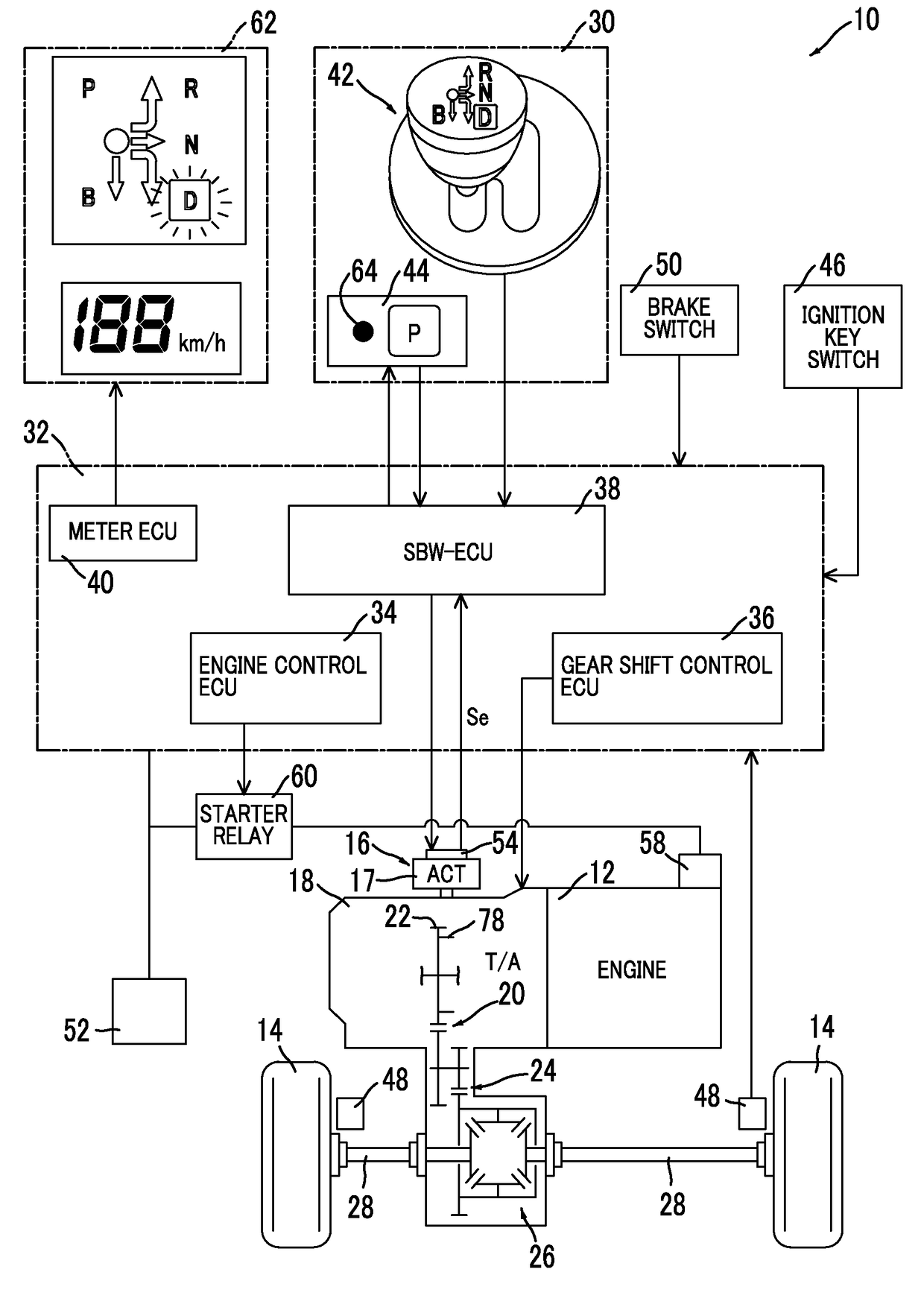
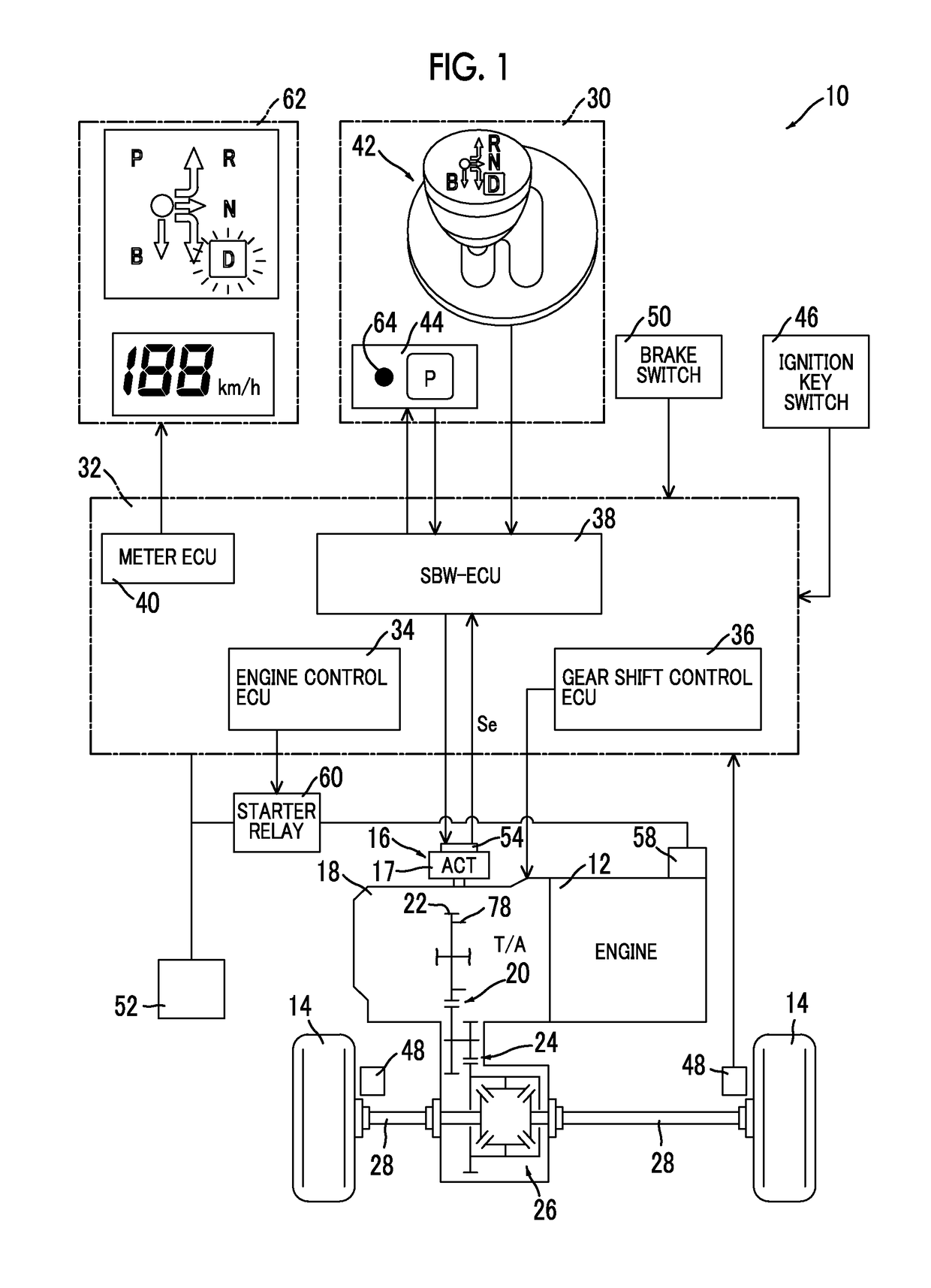
[0034]FIG. 1 is a diagram schematically illustrating a configuration of a power transmission path from an engine 12 to driving wheels 14 in a vehicle 10 to which the present disclosure is applied and is also a block diagram illustrating a principal part of a control system which is disposed in the vehicle 10 to control a shift switching unit 16 (which is illustrated in FIG. 2) and the like. In FIG. 1, the vehicle 10 includes a shift switching unit 16, an electric actuator 17 that drives the shift switching unit 16, an automatic transmission 18, a shift operating unit 30, and an electronic control unit 32, and employs a shift-by-wire (SBW) system that electrically switches a shift position for switching a driving mode associated with traveling of the vehicle 10. The automatic transmission 18 is suitably used, ...


PUM


Abstract

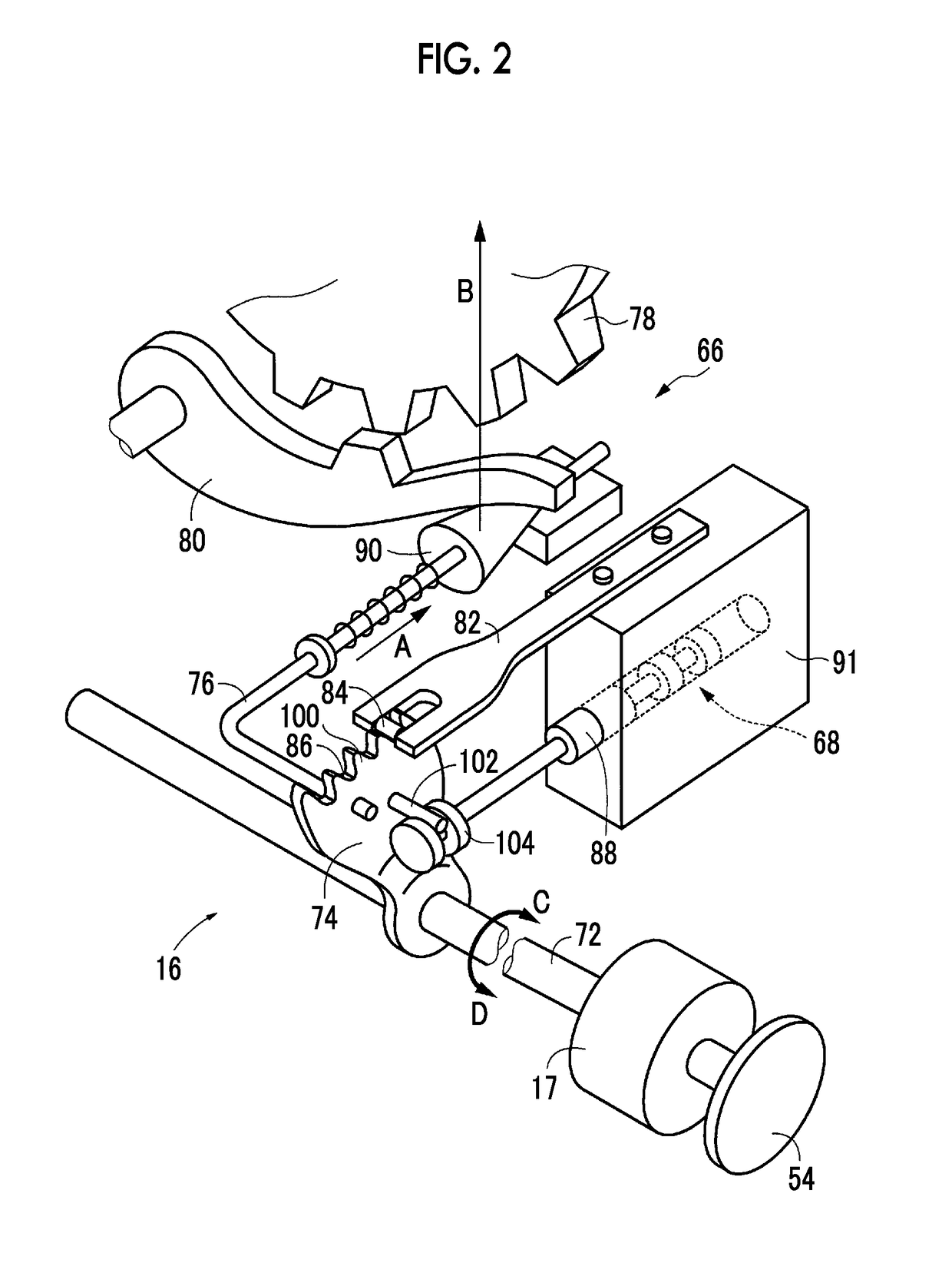
A shift controller for a vehicle includes a shift switching unit, a rotation restricting element, and an electronic control unit. The electronic control unit is configured to: acquire a count value corresponding to a degree of rotation of an actuator; set a rotational position of the actuator when the count value does not change by restricting rotation of the actuator using the rotation restricting element as a reference position of the actuator corresponding to the predetermined shift position; and interrupt setting the reference position of the actuator and restart setting the reference position of the actuator when the rotation of the actuator is restricted and a supply voltage to the actuator is equal to or lower than a predetermined first voltage determination value or a variation in the count value while the rotation of the actuator is restricted is equal to or greater than a predetermined value.

Description

INCORPORATION BY REFERENCE[0001]The disclosure of Japanese Patent Application No. 2016-157035 filed on Aug. 9, 2016 including the specification, drawings and abstract is incorporated herein by reference in its entirety.BACKGROUND1. Technical Field[0002]The present disclosure relates to a shift controller for a vehicle that sets a reference position of an actuator and more particularly to a shift controller that suppresses a decrease in accuracy for setting a reference position of an actuator due to a decrease in voltage supplied to the actuator at the time of performing reference position setting control.2. Description of Related Art[0003]In a vehicle including a shift switching unit configured to switch a shift position of the vehicle to one of a plurality of shift positions by driving an actuator which is supplied with power from a power supply and a rotation restricting element configured to restrict rotation of the actuator in a predetermined direction at a predetermined shift p...

Claims


Application Information

Patent Timeline
IPC IPC(8): F16H63/34F16H63/30F16H61/02
CPCF16H63/3466F16H63/3475F16H61/0213F16H63/3043B60K17/346F16H2059/443F16H2059/0282B60W10/184B60W10/101F16H2061/1292F16H59/12F16H61/12F16H61/28F16H63/3425F16H63/42F16H2061/283F16H2061/326
Inventor KAMADA, ATSUSHIKUBONOYA, HIDEKISAKAGUCHI, KOJIKAWAGUCHI, YUSAKU
Owner TOYOTA JIDOSHA KK
Learn More