

Sealing assembly and plug for non-destructive inspection
- Summary
- Abstract
- Description
- Claims
- Application Information
AI Technical Summary
Benefits of technology
Problems solved by technology
Method used
Image

Examples
Embodiment Construction
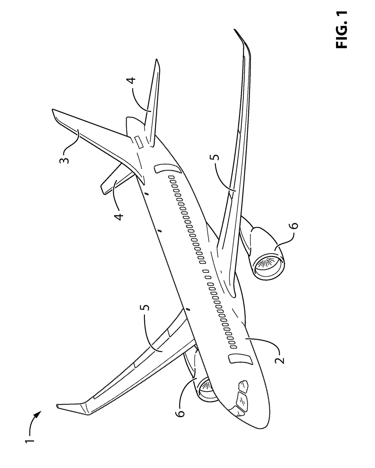
[0043]Referring to the drawings and more particularly to FIG. 1, an aircraft is shown at 1, and is generally described to illustrate some components for reference purposes in the present disclosure. The aircraft 1 has a fuselage 2 having a fore end at which a cockpit is located, and an aft end supporting a tail assembly, with the cabin generally located between the cockpit and the tail assembly. The tail assembly comprises a vertical stabilizer 3 with a rudder, and horizontal stabilizers 4 with elevators. The tail assembly has a fuselage-mounted tail, but other configurations may also be used for the aircraft 1, such as cruciform, T-tail, etc. Wings 5 project laterally from the fuselage. The aircraft 1 has engines 6 supported by the wings 5, although the engines 6 could also be mounted to the fuselage 2. The aircraft 1 is shown as a jet-engine aircraft, but may also be a propeller aircraft.
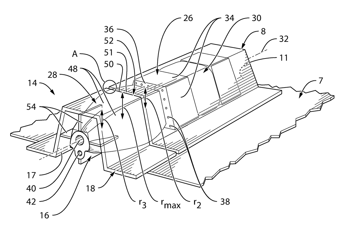
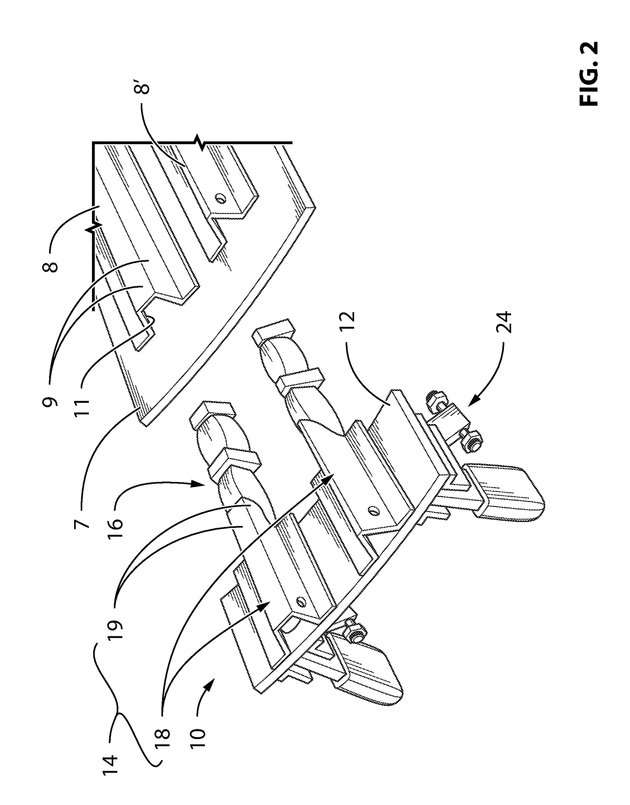
[0044]Referring to FIG. 2, structural components such as for example portions of the fuselage ...
PUM
 Abstract
Description
Claims
Application Information