Seal structure for multi-core cable

a multi-core cable and sealing technology, applied in the direction of electrical apparatus, connection, coupling device connection, etc., can solve the problems of unsatisfactory sealing structure, and need to be said, and achieve the effect of reducing manufacturing costs, increasing contact pressure, and reducing manufacturing costs

Active Publication Date: 2018-02-15
AUTONETWORKS TECH LTD +2
View PDF0 Cites 12 Cited by
  • Summary
  • Abstract
  • Description
  • Claims
  • Application Information

AI Technical Summary

Benefits of technology

[0014]Retaining the electrical wire rubber plug maintains the sealed state of the regions around the electrical wires. If setting is performed such that the electrical wire rubber plug is compressed in the axial direction when the cap is attached, it is possible to increase the contact pressure applied to the electrical wires.
[0015]According to the technology disclosed by this specification, an assembly format is achieved for the seal structure, thereby making it possible to construct the seal structure in a shorter time, and thus making it is possible to reduce manufacturing cost.

Problems solved by technology

With this conventional seal structure, the process of heating and melting the hot-melt resin and then allowing cooling and hardening in particular is time-consuming, and therefore it cannot necessarily be said that this seal structure is satisfactory when taking operation efficiency into account.

Method used


Image

  • Seal structure for multi-core cable
  • Seal structure for multi-core cable
  • Seal structure for multi-core cable

Examples


first embodiment

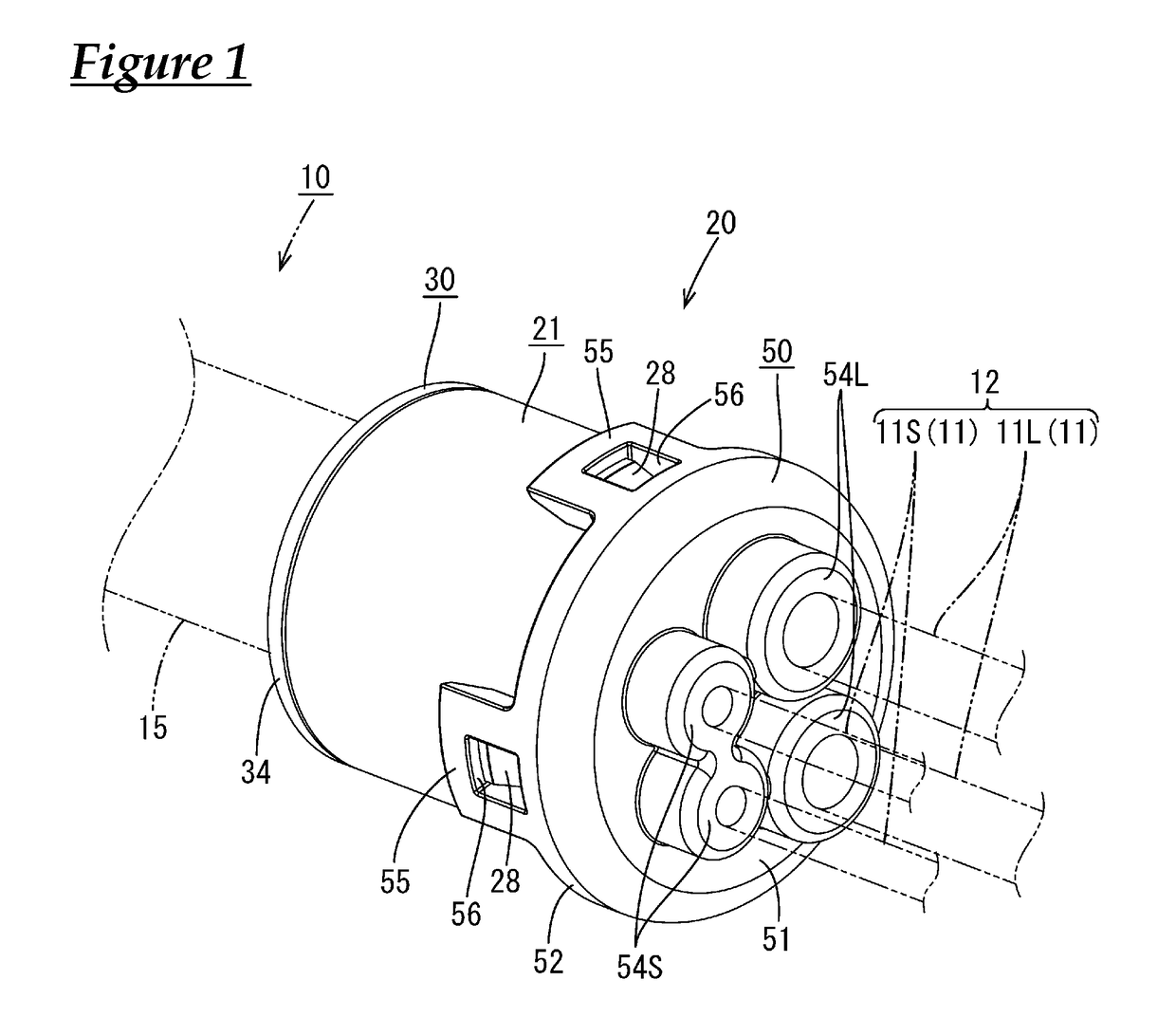
[0034]A first embodiment will be described below with reference to FIGS. 1 to 9. In the present embodiment, a four-core cable is given as an example of a multi-core cable 10, and application as, for example, a wire harness for an electrical parking brake installed in a vehicle is possible.

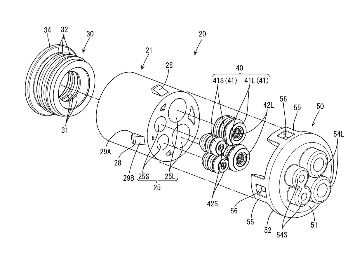
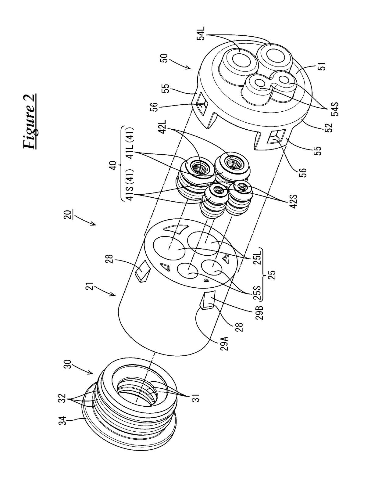
[0035]As shown in FIG. 1, a seal structure is constructed by attaching a seal member 20 to a terminal portion of the multi-core cable 10.

[0036]The multi-core cable 10 is a four-core round cable as described above, and has a structure in which four electrical wires 11 (referred to as a group of electrical wires 12 when appropriate) are enveloped by a sheath 15 that is made of an insulating resin. The electrical wires 11 are each a sheathed electrical wire constituted by a metal core wire that is covered by an insulating covering made of a synthetic resin, and the electrical wires 11 include two each of two types of electrical wires 11L and 11S that have different outer diameters. The two first elect...

second embodiment

[0060]A second embodiment will be described below with reference to FIGS. 10 to 18. In the first embodiment, the electrical wire rubber plug 40 is constituted by four individual rubber plugs 41, but a difference in the second embodiment is that an electrical wire rubber plug 70 is constituted by an integrated rubber plug. The following description focuses on differences, and members and portions having the same functions as in the first embodiment are appropriately given the same reference signs, thereby omitting or simplifying redundant descriptions.

[0061]The electrical wire rubber plug 70 of the present embodiment is an integrated rubber plug as described above, and as shown in FIG. 11, has a structure in which two first through-holes 73L and two second through-holes 73S, through which the larger-diameter first electrical wires 11L and the smaller-diameter second electrical wires 11S respectively pass, are formed in a single rubber plug main body 71.

[0062]More specifically, as sho...


PUM


Abstract

A multi-core cable in which electrical wires are enveloped by a sheath, a sheath rubber plug that is fitted around the terminal of the sheath, an electrical wire rubber plug through which the electrical wires, which extend from the terminal of the sheath, individually pass, and a housing that has attachment holes into which the sheath rubber plug and the electrical wire rubber plug are respectively fitted.

Description

CROSS REFERENCE TO RELATED APPLICATIONS[0001]This application claims the priority of Japanese patent application JP2015-040018 filed on Mar. 2, 2015, the entire contents of which are incorporated herein.TECHNICAL FIELD[0002]The technology disclosed in this specification relates to a seal structure for a multi-core cable.BACKGROUND ART[0003]A multi-core cable has a structure in which a plurality of electrical wires are covered by a sheath that is made of an insulating resin material, and, conventionally, a seal structure (water stop structure) for the terminal portion of a multi-core cable is disclosed in JP 2012-182924A (referred to as Patent Document 1 hereinafter). In this seal structure, terminal processing is performed on the multi-core cable to branch off each electrical wire from the terminal of the sheath, a hot-melt block that includes partition walls for partitioning the electrical wires from each other is attached to the branched-off electrical wires, and then a heat-shrin...

Claims


Application Information

Patent Timeline
Patent Type & Authority Applications(United States)
IPC IPC(8): H01R9/11H01R4/70
CPCH01R9/11H01R4/70H01R13/5205H01R13/5208H01R13/5213
Inventor KOMORI, HIROKAZUSAKATA, TOMOYUKIHIGASHIKOZONO, MAKOTO
Owner AUTONETWORKS TECH LTD
Why Eureka
Try Eureka